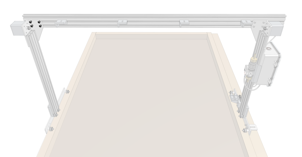
Construct the Gantry
Step 1: Assemble the main beam
This step applies to XL and MAX kits only. If you are assembling a standard sized Express kit, skip to step 2.
Insert four 60mm nut bars into the lower two slots in each of the gantry main beam subassemblies on the same side of the extrusions as the cable carrier supports.
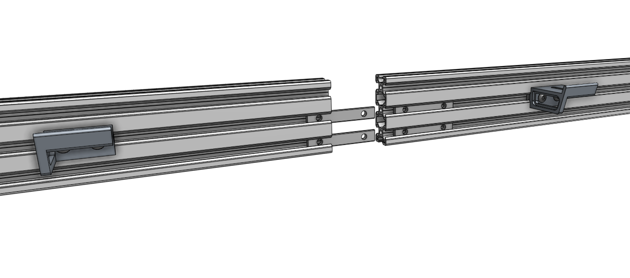
Find a flat surface
The next steps require a flat surface such as a table or patio.
Place both gantry main beam subassemblies on a flat surface, end-to-end. Position the gantry joining bracket such that the notch in the bottom of the bracket is aligned with the joint between the two main beams. Then insert and tighten eight M5 x 10mm screws.
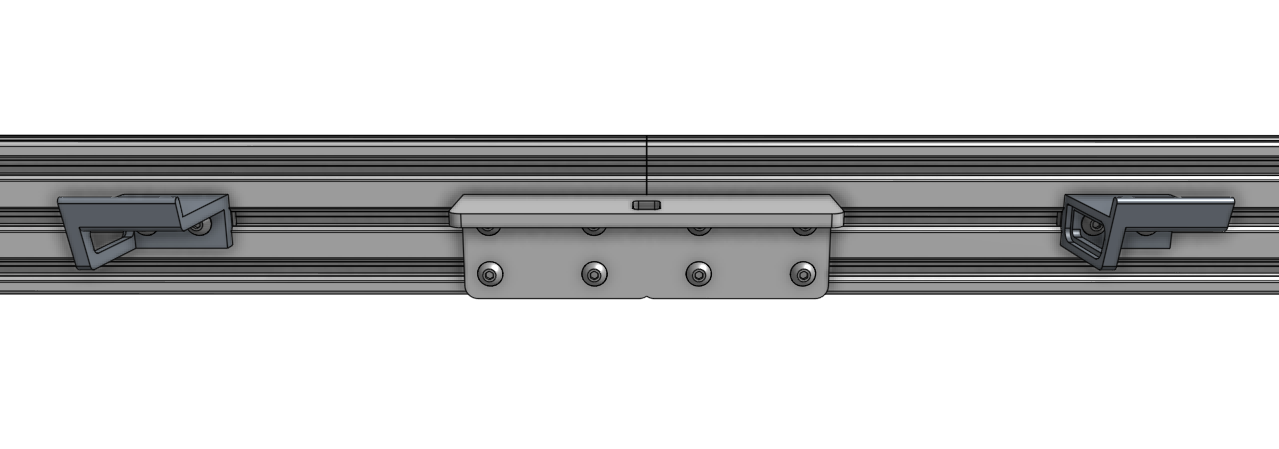
The completed main beam for XL and MAX bots should now look like this. Note that in the rest of the documentation we’ll be showing images of the standard sized main beam, but all the instructions are the same from here on out.

Step 2: Attach the gantry columns
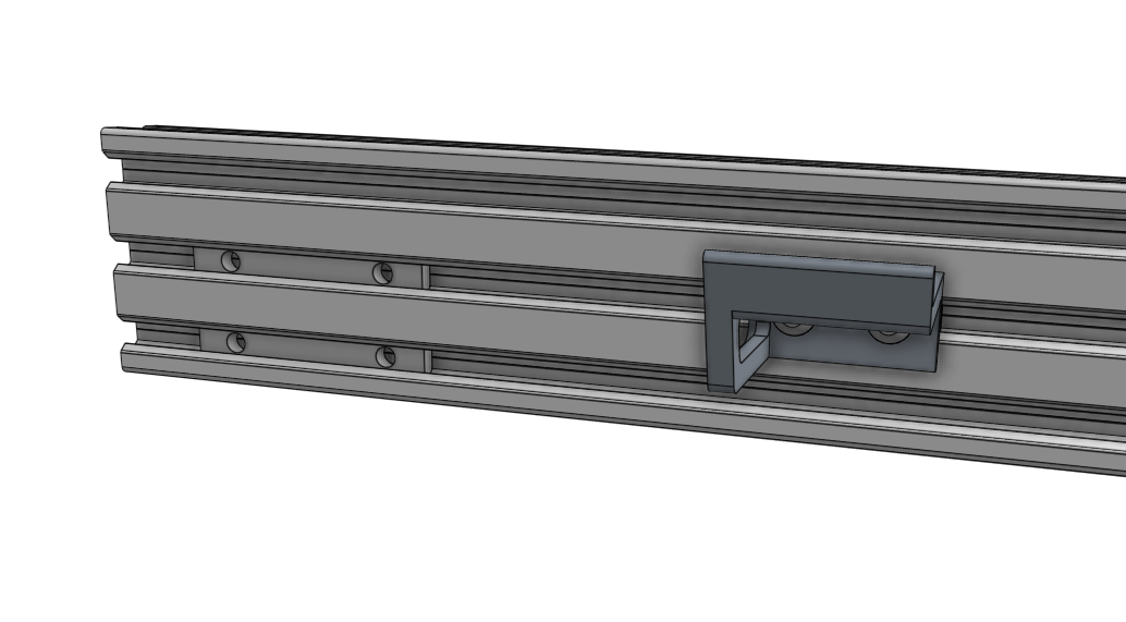
Insert two 60mm nut bars into the lower two slots on the backside of the gantry main beam.
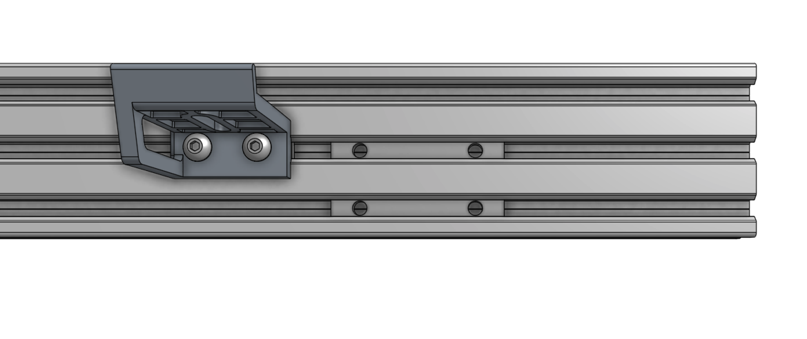
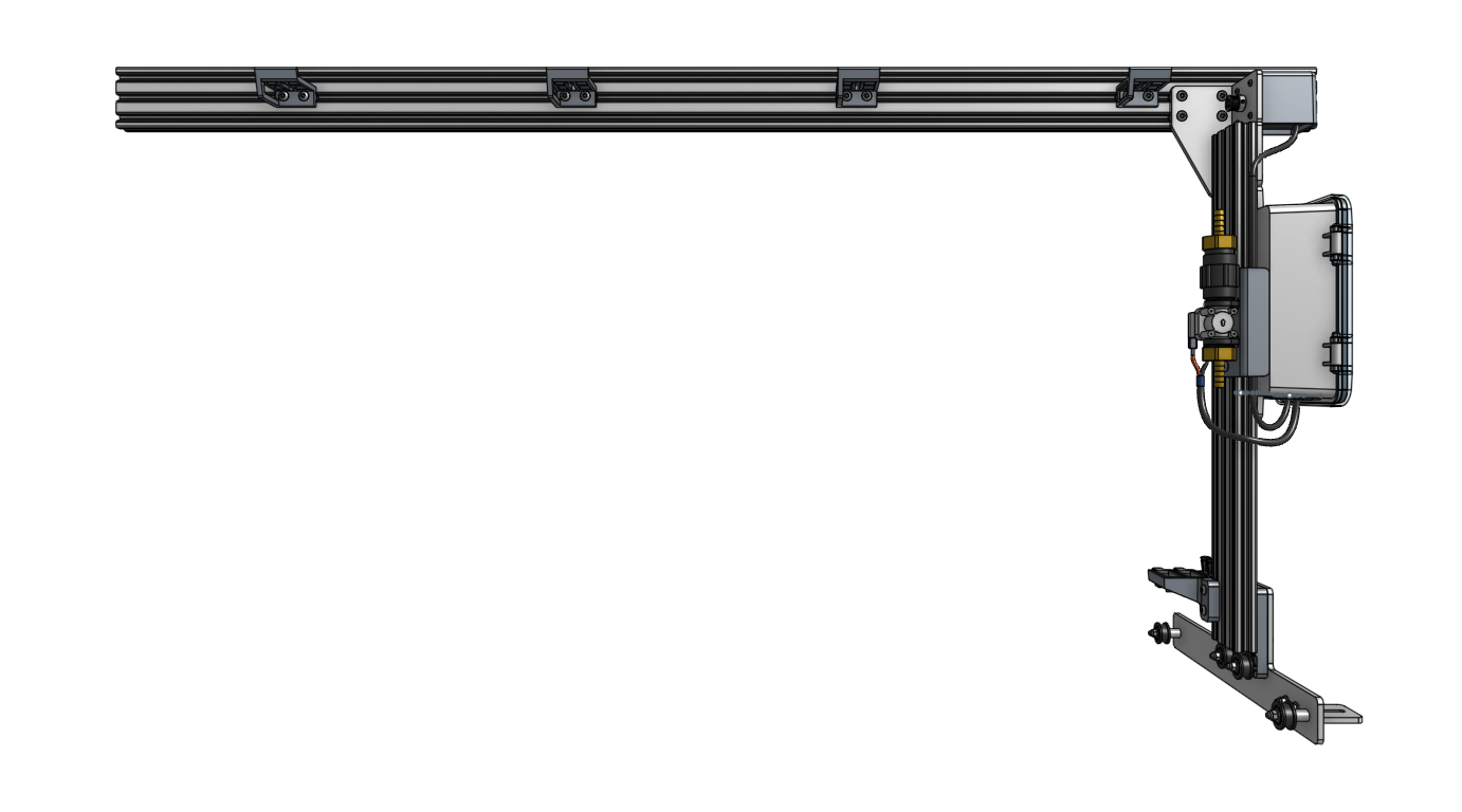
Position the left gantry column subassembly (the one with the electronics box) as shown and use four M5 x 10mm screws to loosely attach it to the gantry main beam. The screws should only be tightened 50% of the way such that the column will not fall off, but so that it can still be moved within the main beam’s slots.
Note that in the images below, we are looking at the FarmBot from the back side, so the left gantry column subassembly appears on the right of the image.
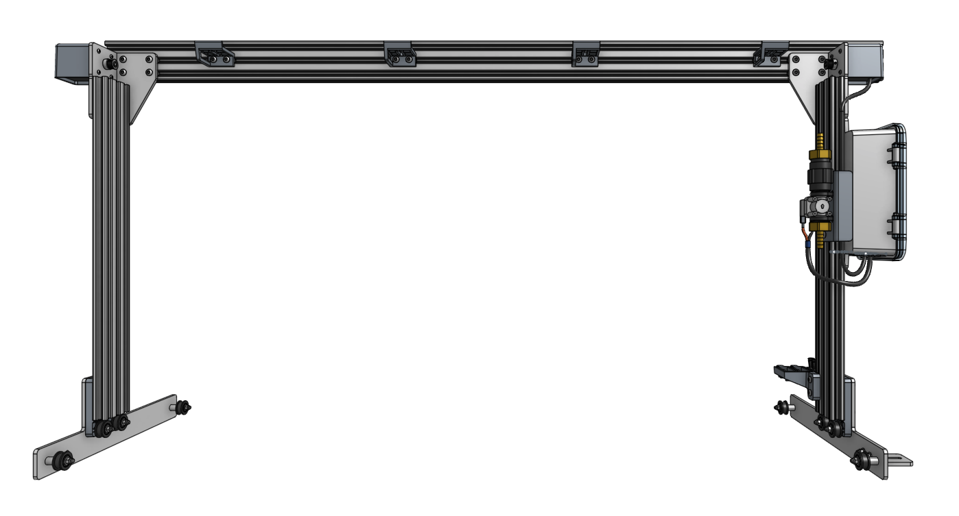
Repeat the steps above with the right gantry column subassembly.

Step 3: Fit FarmBot to the bed
Carefully move the gantry and position it onto the raised bed. Slide the columns along the main beam’s extrusion slots until each column’s wheel plate is positioned against the outer faces of the bed.
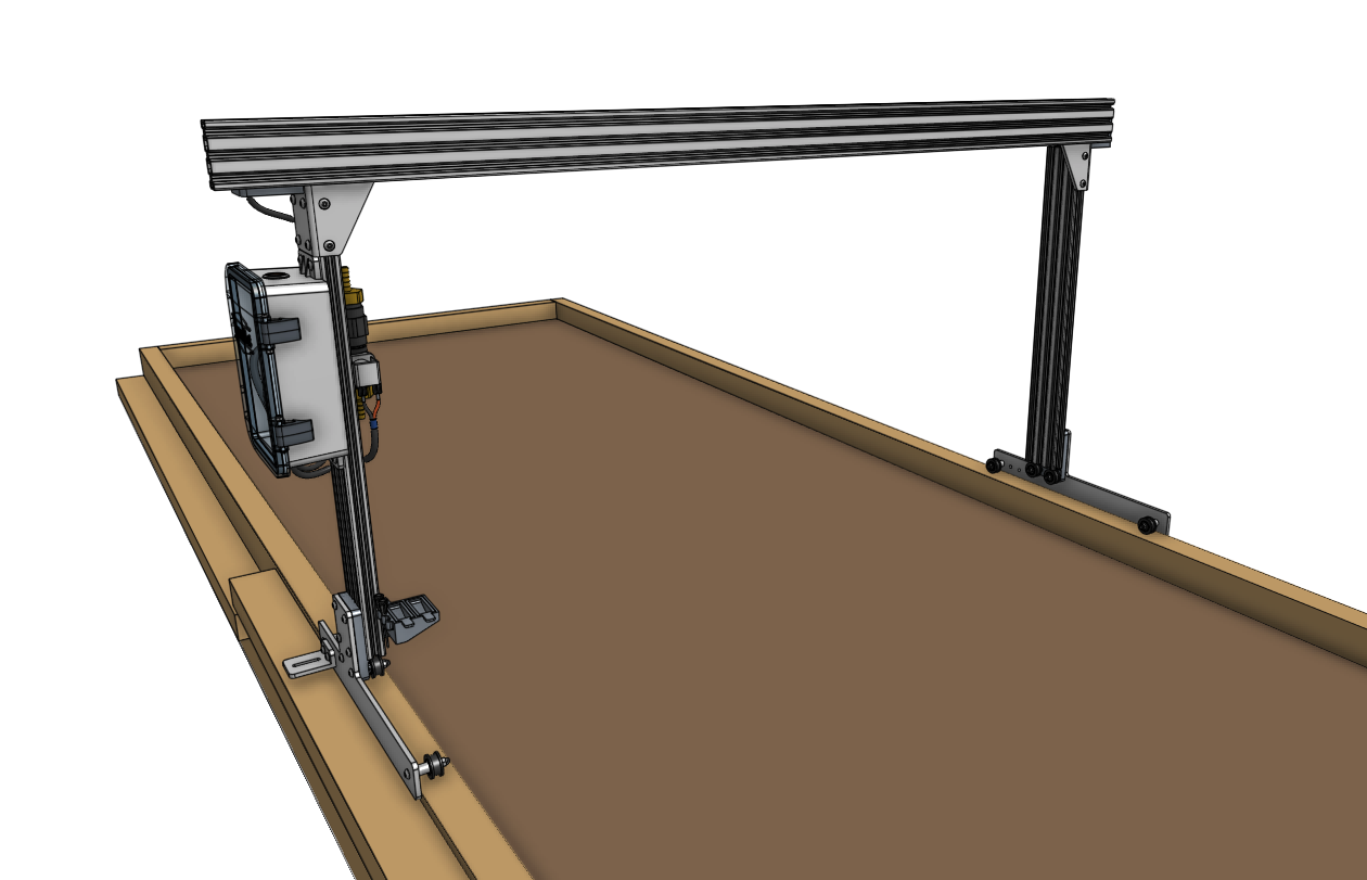
Ensure one of the columns is perpendicular to the main beam and then fully tighten the four screws to firmly fasten the column to the main beam.
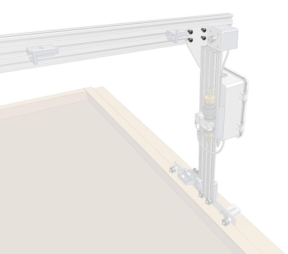
Ensure the fastened column’s wheel plate is pressed against the outer face of the bed.
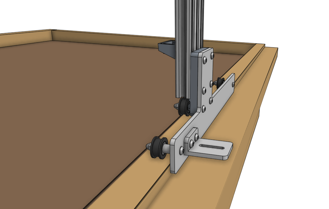
Slide and position the second column such that it is perpendicular to the main beam, and so that there is 1cm of space between the outer face of the bed and the inner face of the wheel plate.
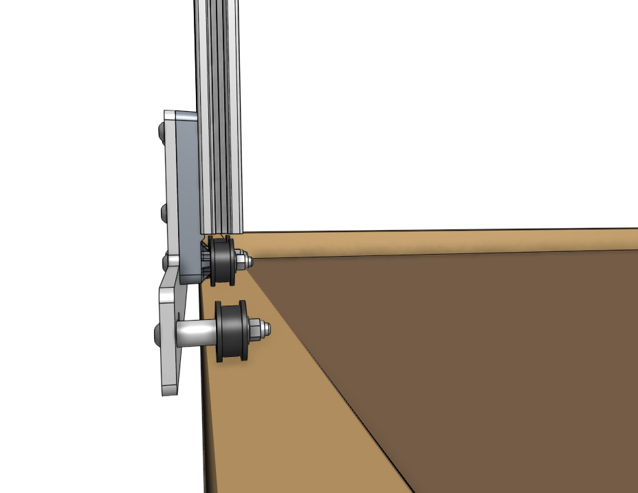
Tighten the four screws holding the second column to the main beam.
