Electronics Box
Pre-assembly instructions for the FarmBot Express and Express XL electronics box
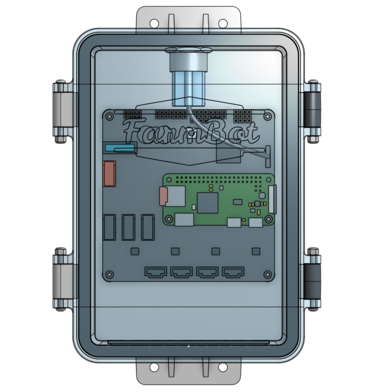
Component list
| Component | Qty |
|---|---|
| Electronics Box (Box) | 1 |
| Electronics Box (Lid) | 1 |
| Electronics Box (Gasket) | 1 |
| Electronics Box (Latch) | 2 |
| Electronics Box (Supergland Half) | 2 |
| Farmduino Express | 1 |
| Raspberry Pi Zero 2 W | 1 |
| micro SD card | 1 |
| E-Stop Button | 1 |
| E-Stop Button Wiring Harness | 1 |
| M3 x 35mm Screws | 4 |
| M3 Locknuts | 4 |
| Standoffs (M2.5 x 11mm F/F) | 2 |
| M2.5 x 4mm Screws | 8 |
Step 1: Mount the Pi to the Farmduino
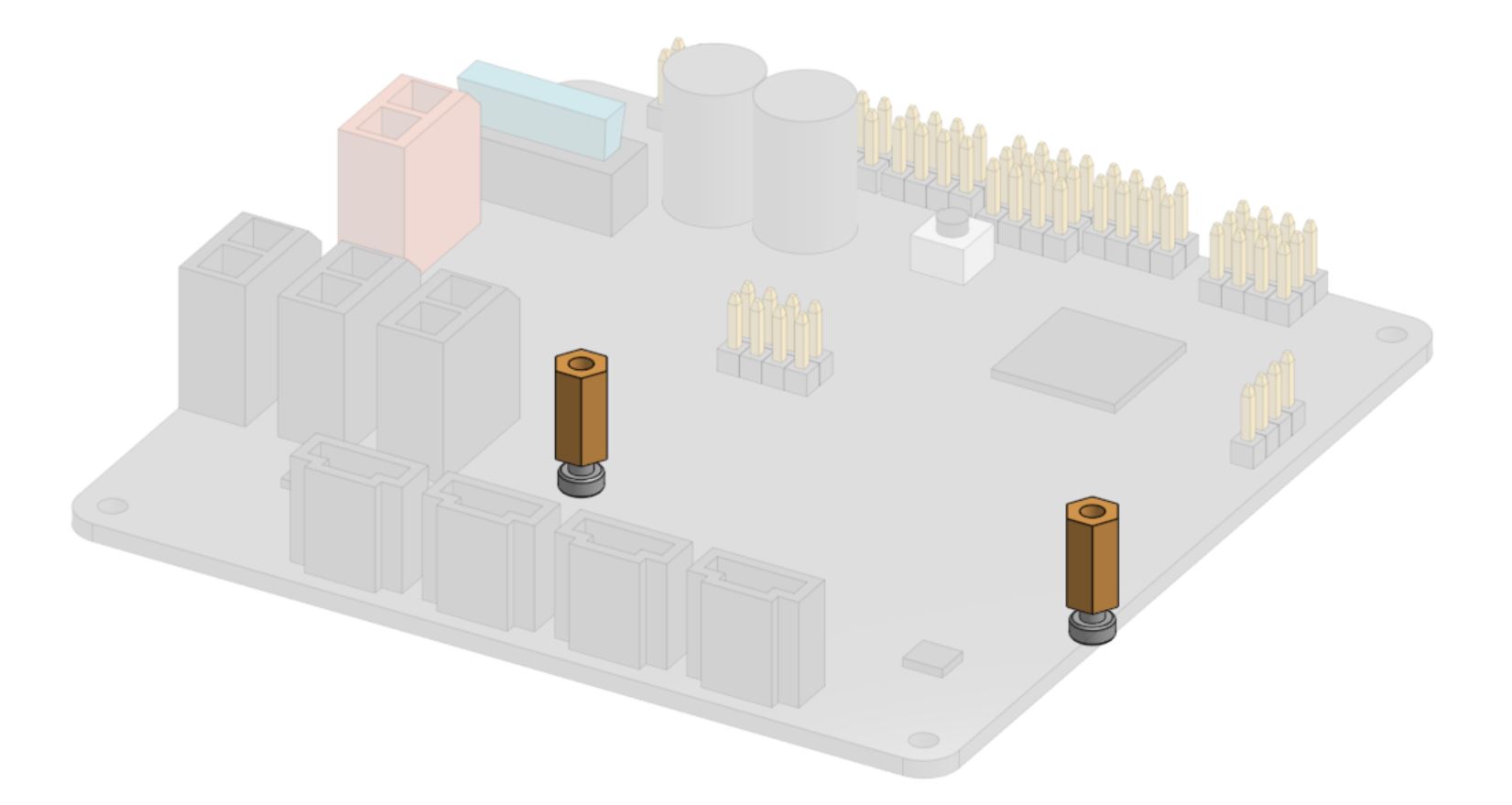
Mount the two standoffs to the Farmduino Express board using two M2.5 x 4mm screws.
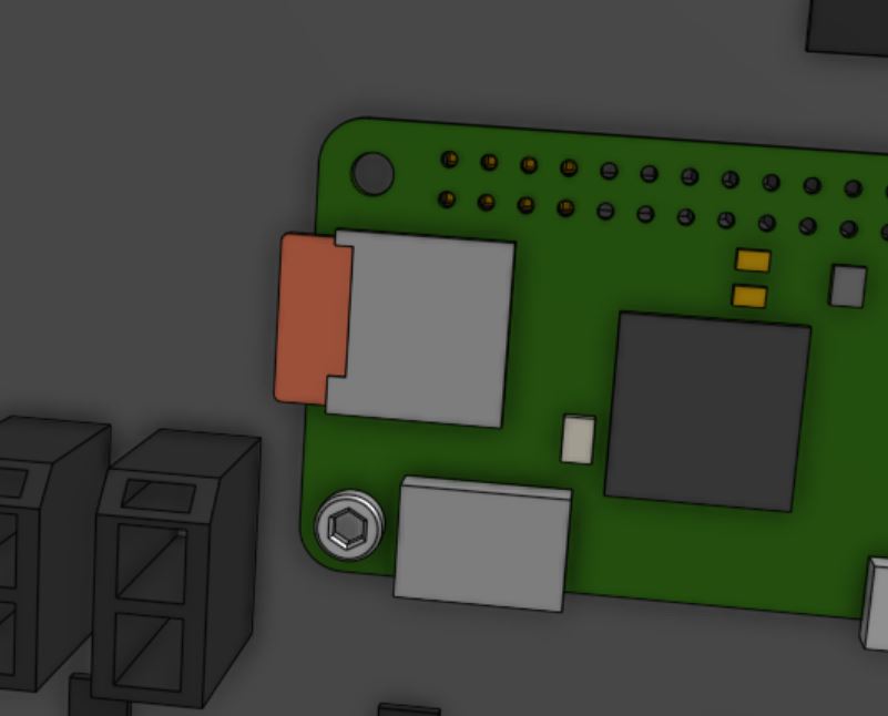
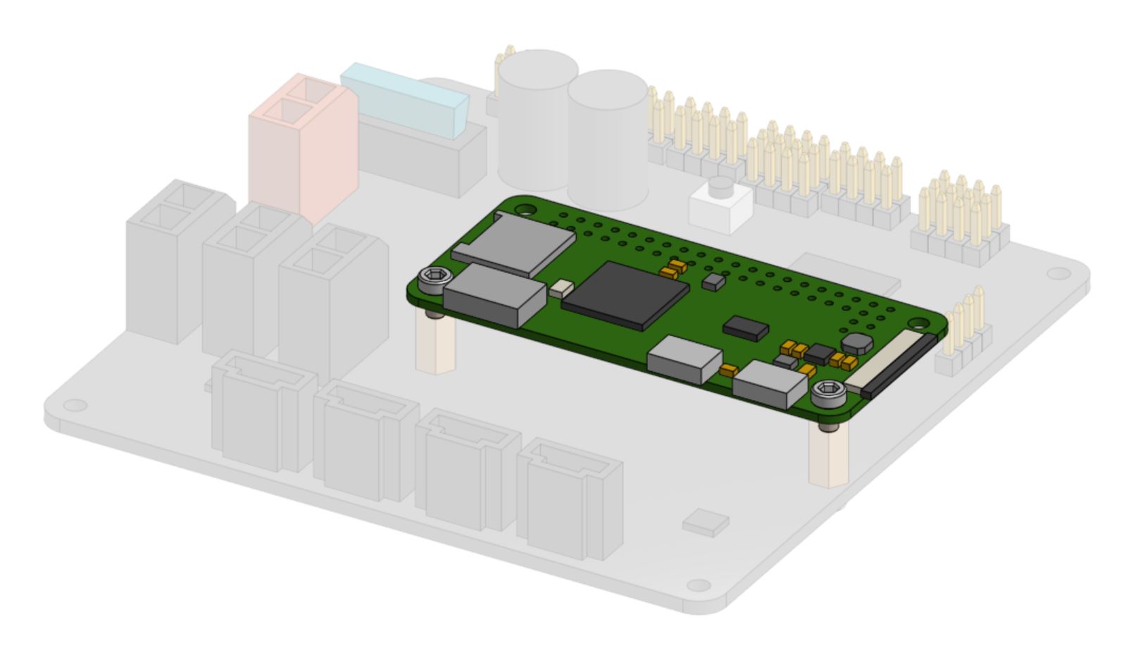
Mount the Raspberry Pi Zero 2 W onto the Farmduino Express by pressing the Pi’s GPIO pins into the Farmduino’s pin header. Be careful not to bend any pins.
Then secure the Pi using two M2.5 x 4mm screws screwed into the standoffs.
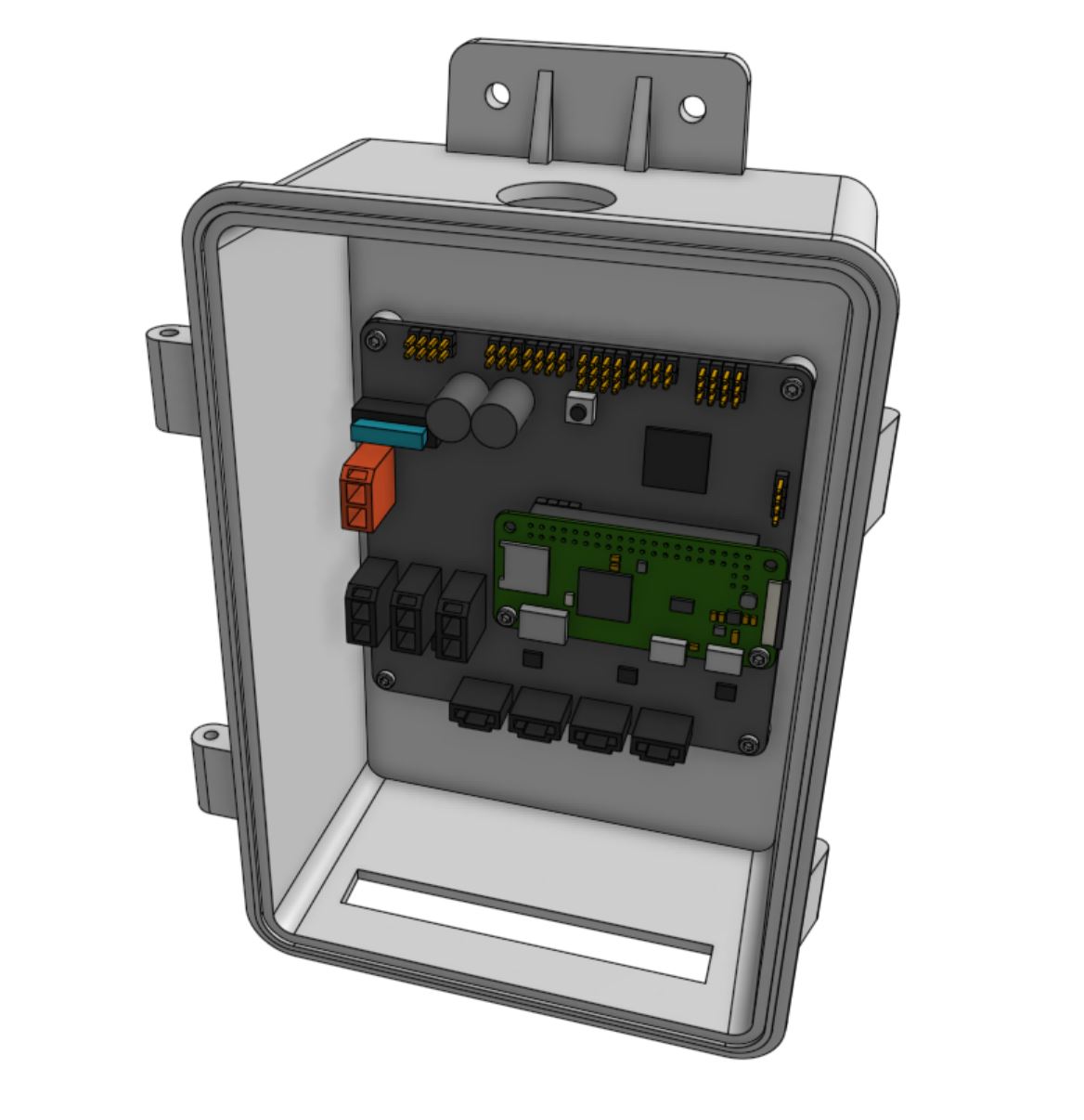
Step 2: Mount the electronics in the box
Mount the Farmduino Express in the electronics box using four M2.5 x 4mm screws.
Step 3: Insert the E-stop button
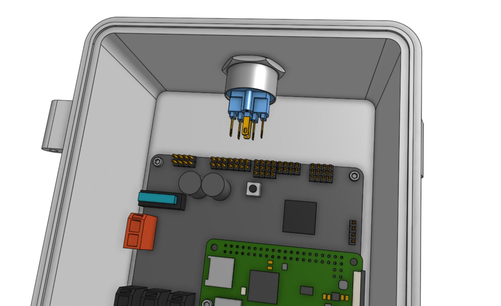
Insert the E-stop button into the large hole in the top of the electronics box. Secure it with the locking ring, ensuring the locking tab is facing towards you (out of the front of the box).
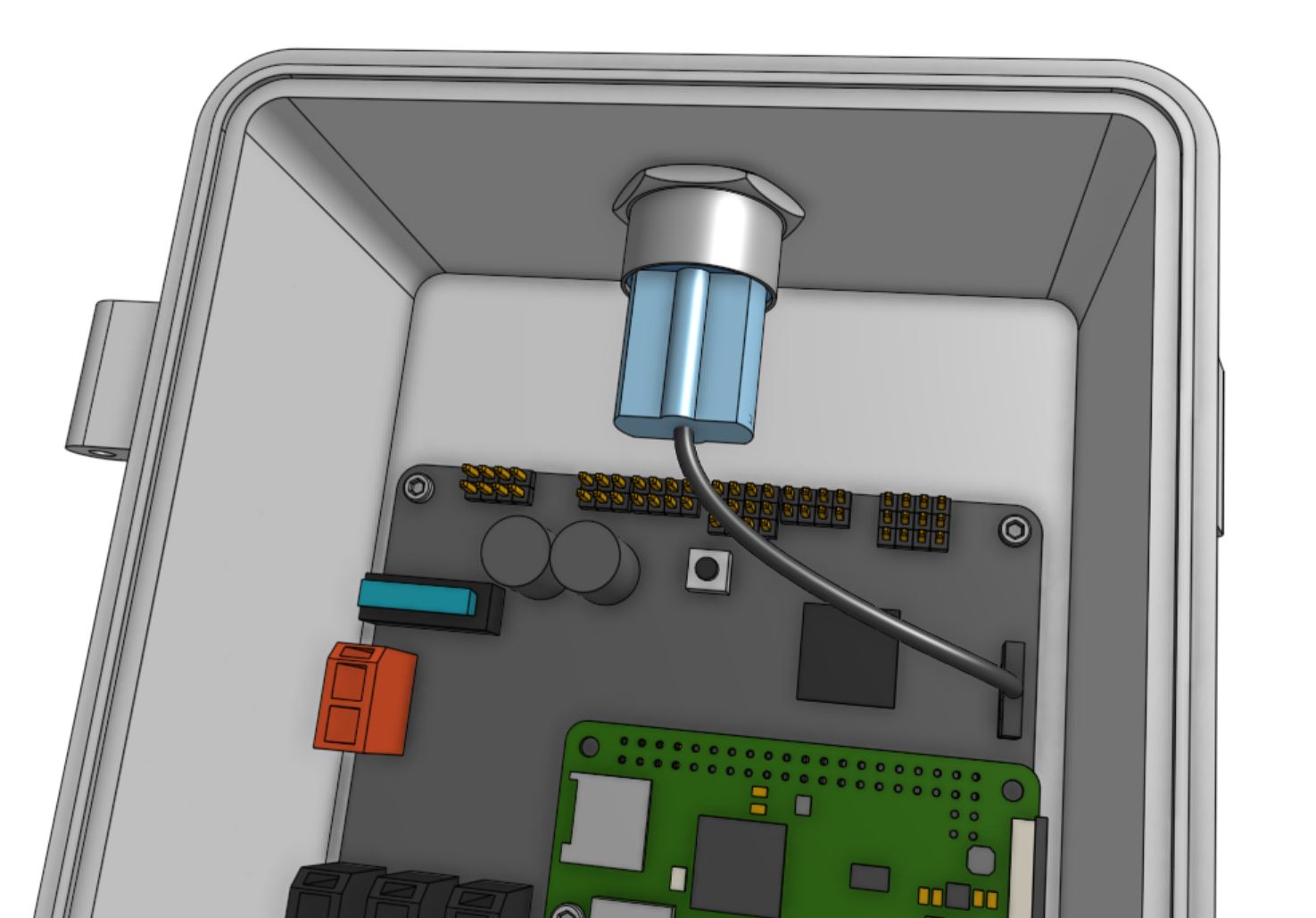
Attach the E-stop button wiring harness to the E-stop button and the E-STOP pin header located on the right side of the Farmduino Express board. The wiring harness release tab should be facing towards you (out of the front of the box).
Step 4: Insert the supergland
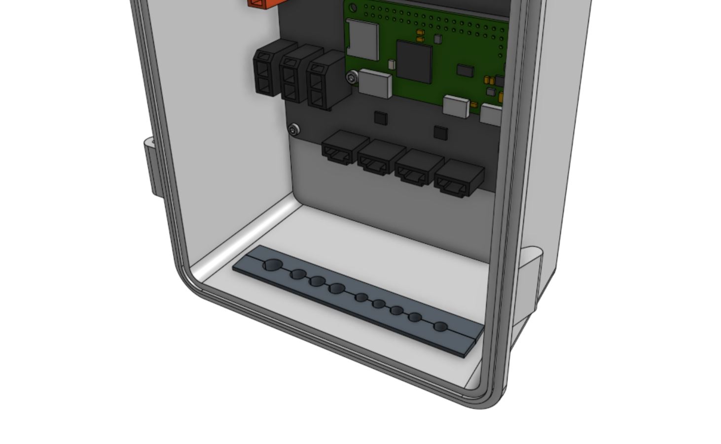
Insert the two supregland halves into the slot in the bottom of the electronics box. The largest hole in the supergland should be positioned on the left side of the box.
Step 5: Prepare the lid
Press the electronics box gasket into the electronics box lid, ensuring the gasket seats fully into the slot.
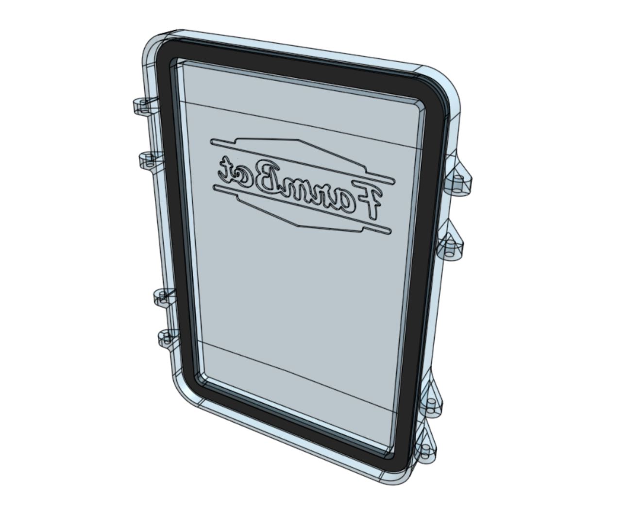
Attach the two electronics box latches to the electronics box lid using two M3 x 35mm screws and M3 locknuts. The latches should be on the right side of the lid (when the logo is facing towards you). The locknuts should be located on the inside mounting tabs while the screw heads should be located on the outside mounting tabs.
Do not overtighten the screws
Tighten the screws and locknuts just enough to make sure the screw cannot slide in the mounting tabs. The mounting tabs should not be bending or causing friction.
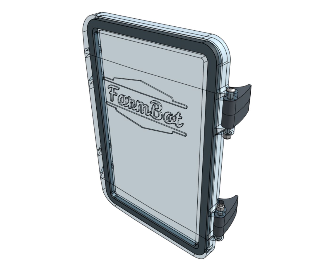
Step 6: Attach the lid
Attach the electronics box lid to the electronics box using two M3 x 35mm screws and M3 locknuts. The locknuts should be located on the inside mounting tabs while the screw heads should be located on the outside mounting tabs.
Do not overtighten the screws
Tighten the screws and locknuts just enough to make sure the screw cannot slide in the mounting tabs. The mounting tabs should not be bending or causing friction.
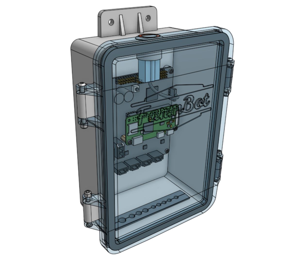
Step 7: Insert the microSD card
Once FarmBot OS has been loaded onto the micro SD card, insert the card into the Pi.
