Right Gantry Column
Pre-assembly instructions for the FarmBot Express and Express XL right gantry column
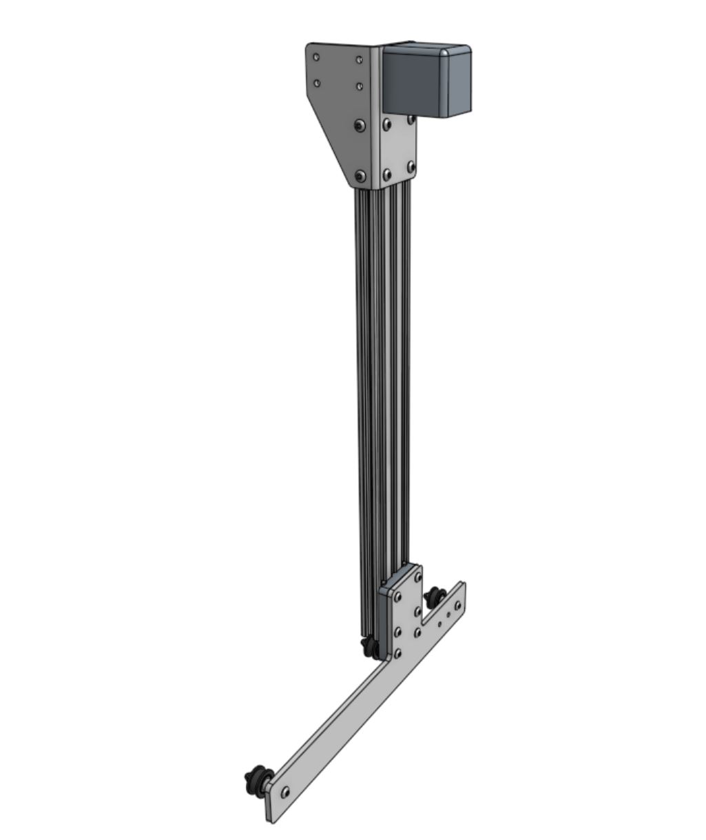
Component list
Step 1: Mount the idler pulleys
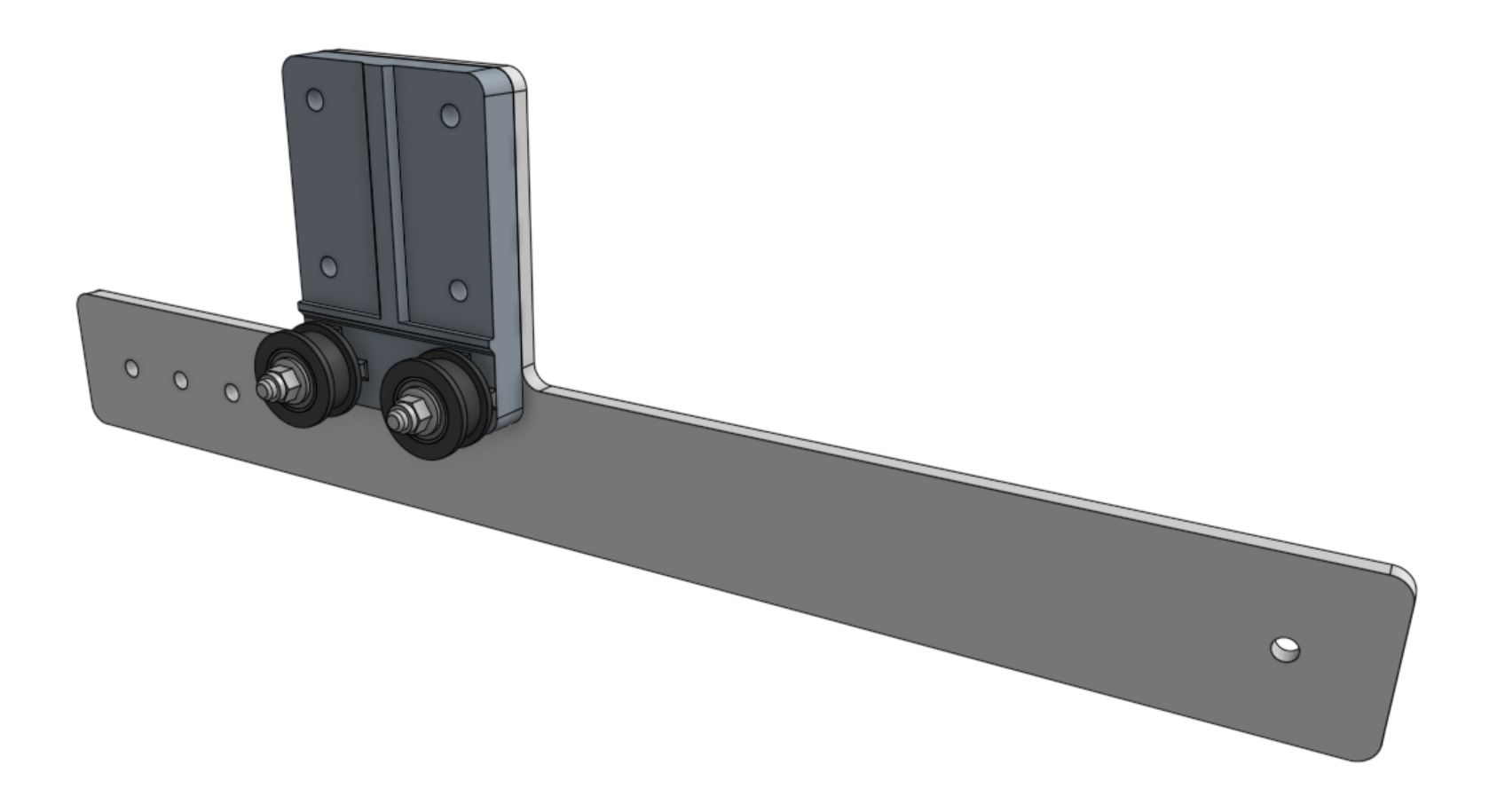
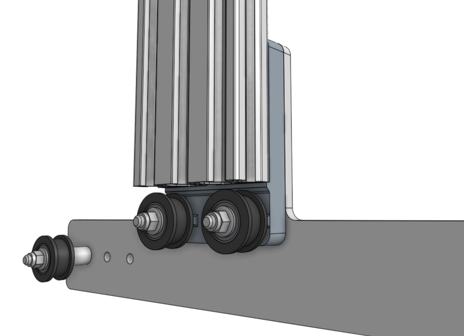
Mount two idler pulleys to the gantry wheel plate using two M5 x 40mm screws, two M5 flange locknuts, and the gantry plate spacer block as a spacer.
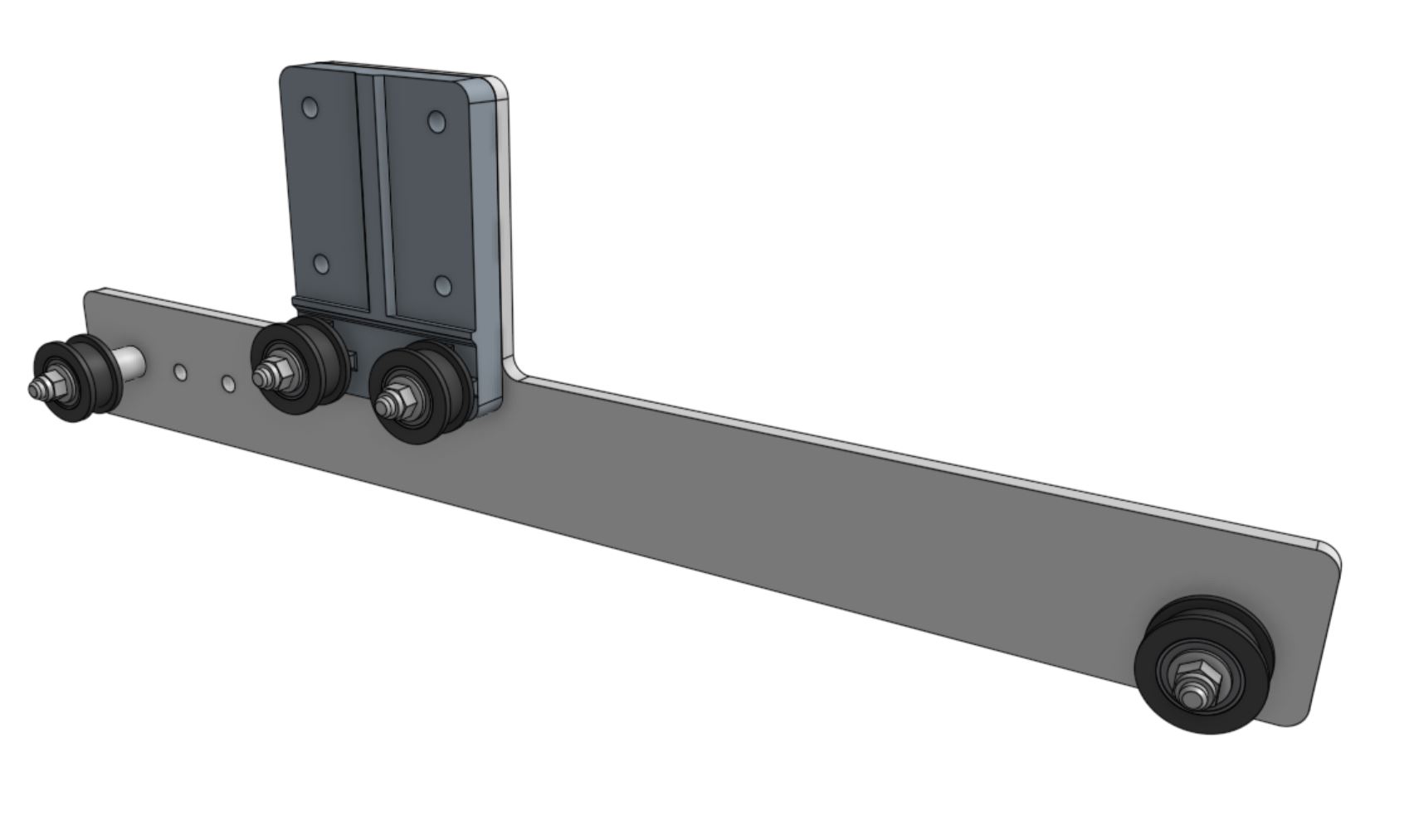
Mount the other two idler pulleys with M5 x 40mm screws and M5 flange locknuts, this time using two M5 x 14.5mm spacers.
Step 2: Attach the gantry column
Lightly screw four M5 x 20mm screws to two 60mm nut bars. The nut bars should be loose enough to slide into the end of an extrusion in the next step.
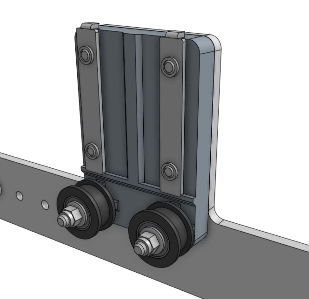
Slide the gantry column onto the assembly, ensuring the cut end of the extrusion fits flush against the horizontal stop on the gantry plate spacer block. Then tighten the four M5 x 20mm screws.
Step 3: Attach the gantry corner bracket
Attach the right gantry corner bracket to the gantry column using three 60mm nut bars and six M5 x 10mm screws. The top of the extrusion should be aligned with the notch in the corner bracket.
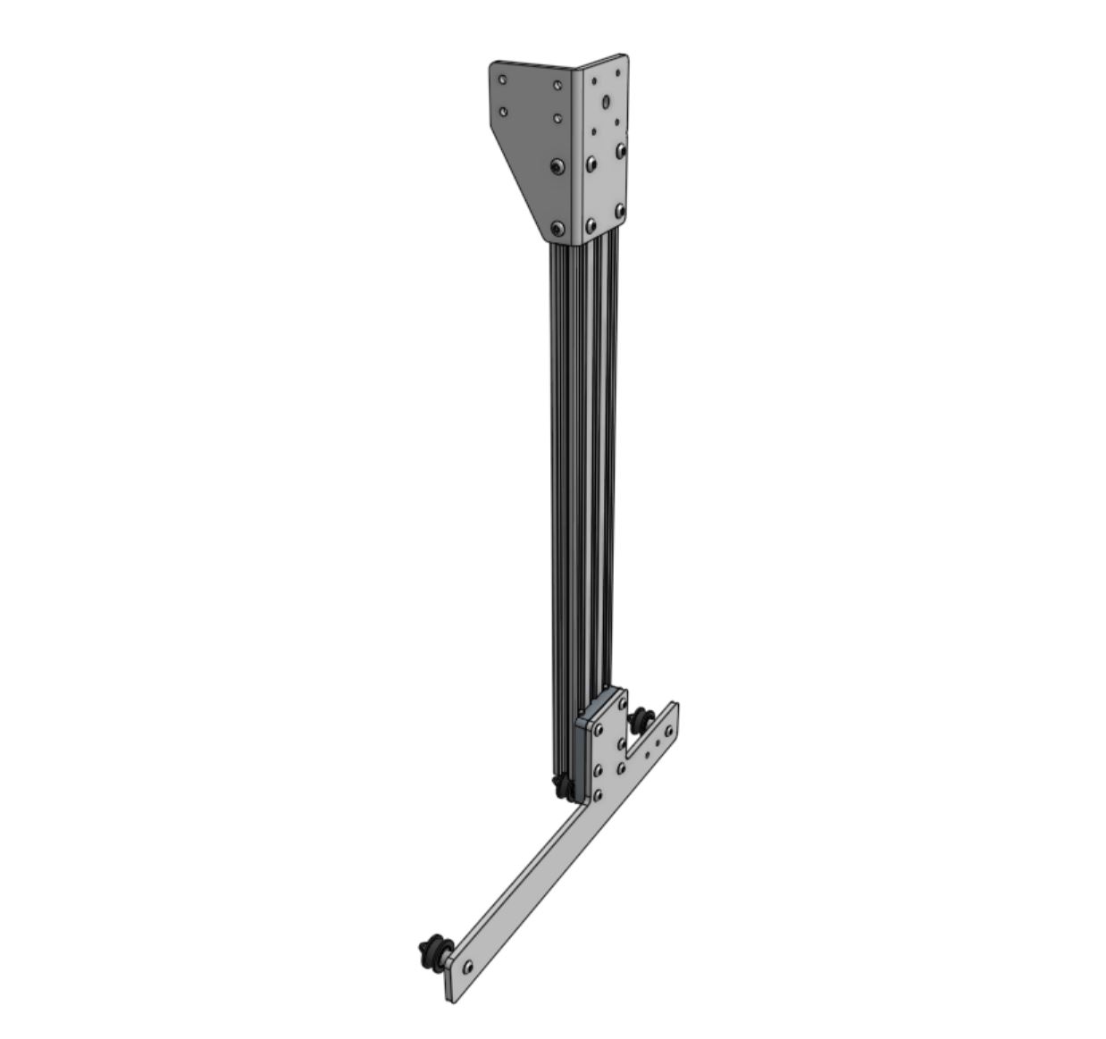

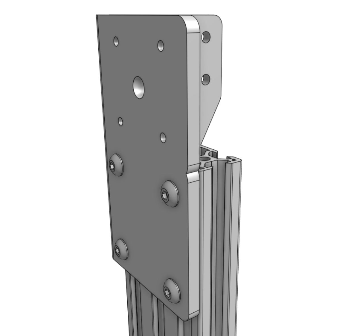
The top of the extrusion should be aligned with the notch in the corner bracket.
Step 4: Attach the X2 motor
Insert the shaft of the motor into the hole in the center of the gantry corner bracket. The motor connector should be facing down, towards the gantry wheel plate.
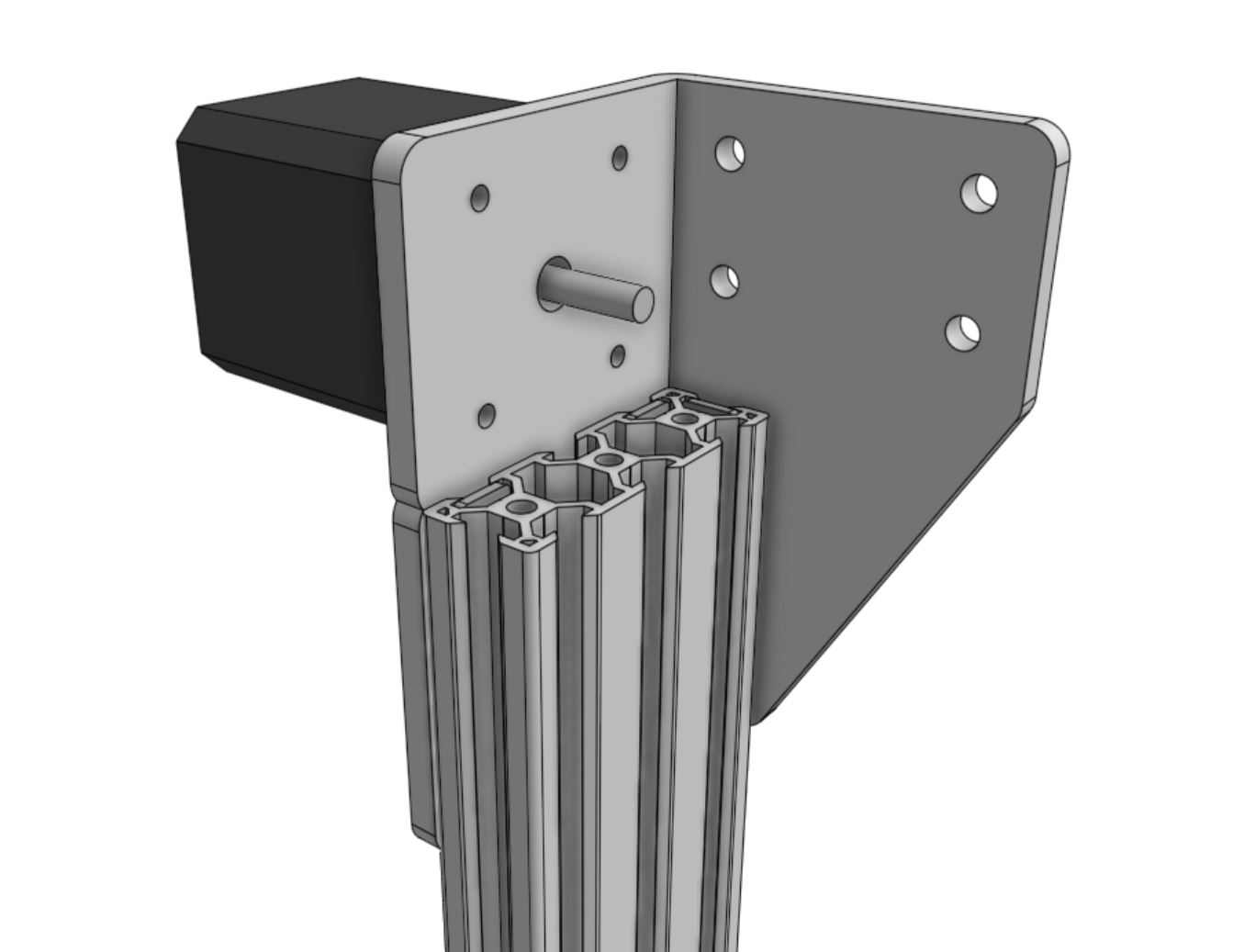
Slide the horizontal motor housing over the top of the motor. The open end of the motor housing should be facing down, towards the gantry wheel plate.
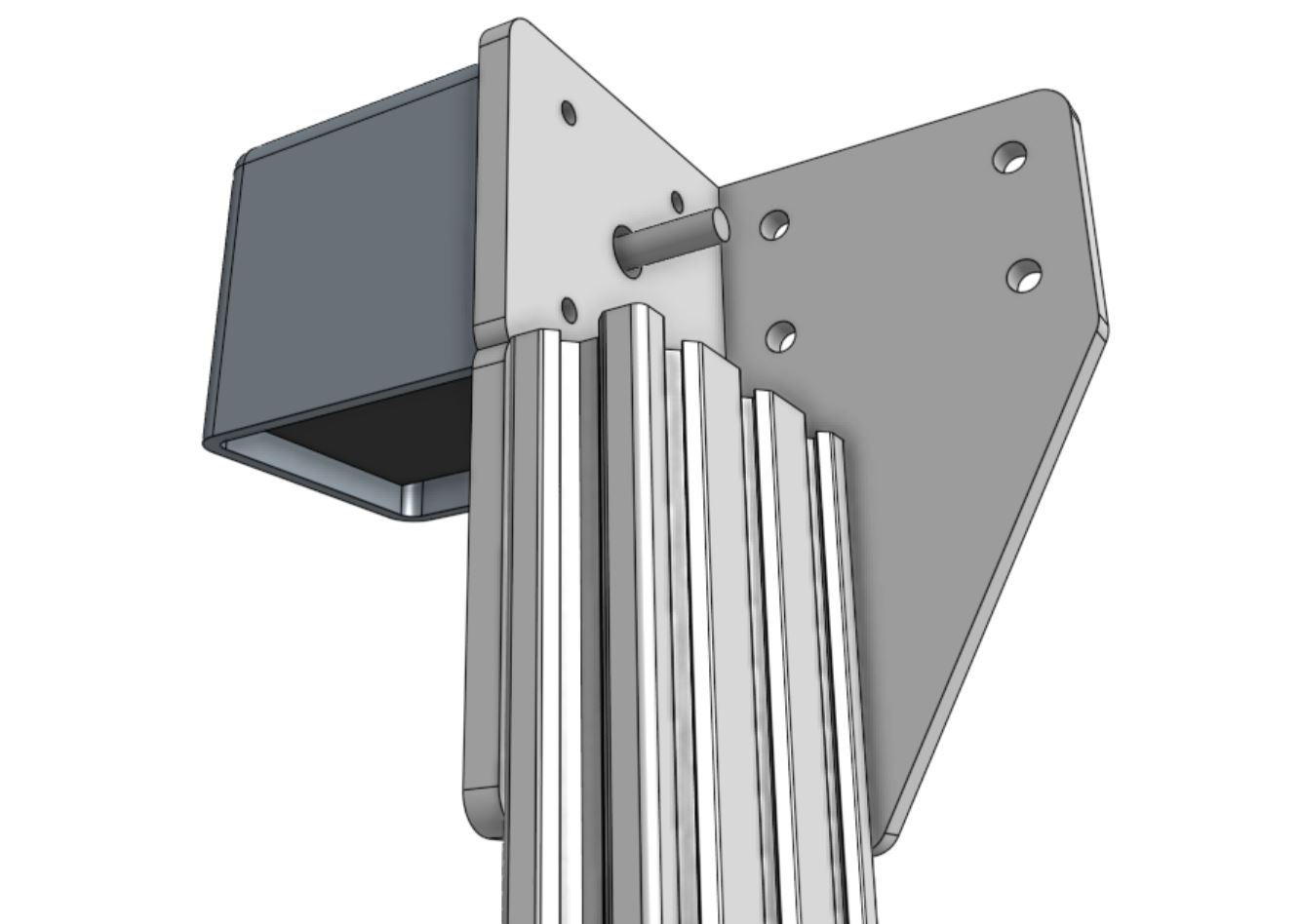
Secure the motor and housing in place with four M3 x 12mm screws.
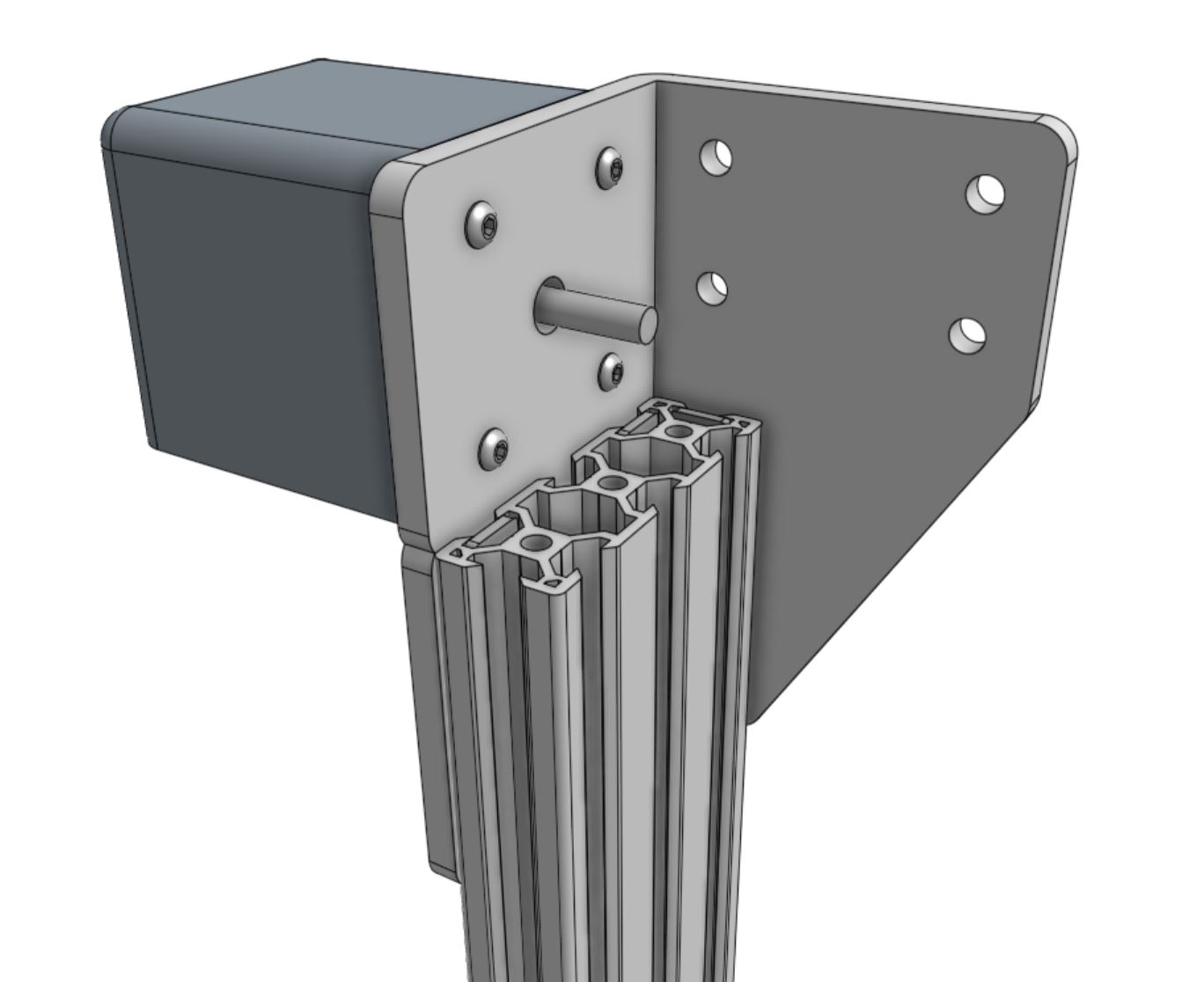
Slide the pulley onto the motor shaft, ensuring the two setscrews are aligned with the flat sides of the motor shaft. The pulley’s toothed area should be aligned with the large holes in the extrusion such that the belt can be routed through the extrusion without rubbing. Then tighten the setscrews.
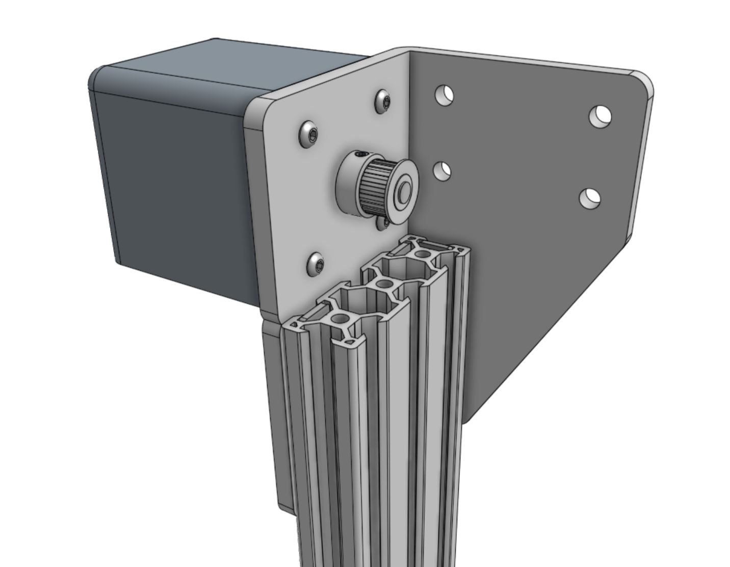

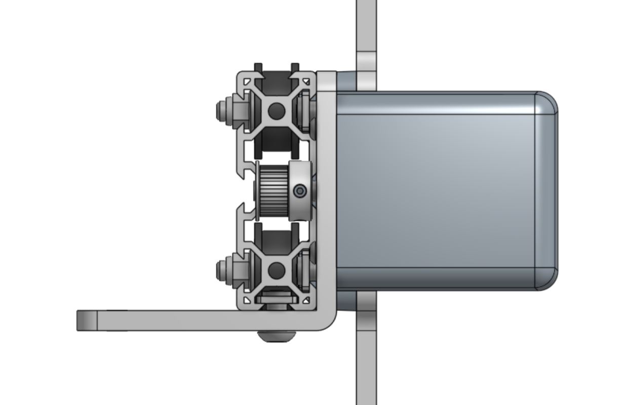
The pulley’s toothed area should be aligned with the large holes in the extrusion such that the belt can be routed through the extrusion without rubbing.