Z-Axis
Pre-assembly instructions for the FarmBot Express and Express XL Z-axis
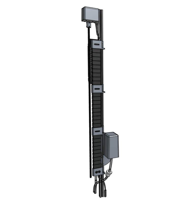
Component list
Step 1: Mount the vacuum pump
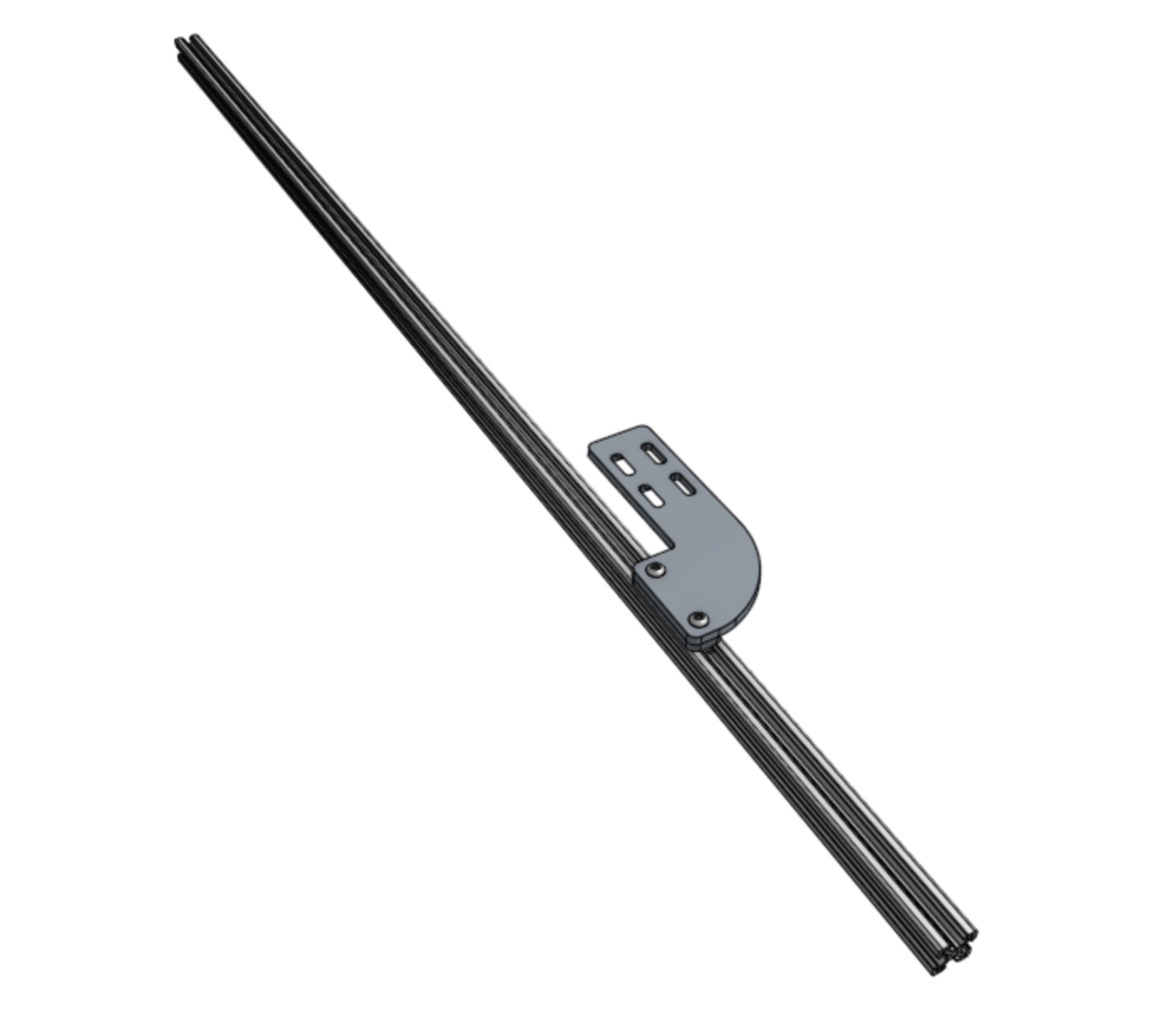
Attach the vacuum pump mount to the the z-axis extrusion using two M5 x 16mm screws and one 60mm nut bar. The bottom of the mount should be 185mm from the bottom of the extrusion.
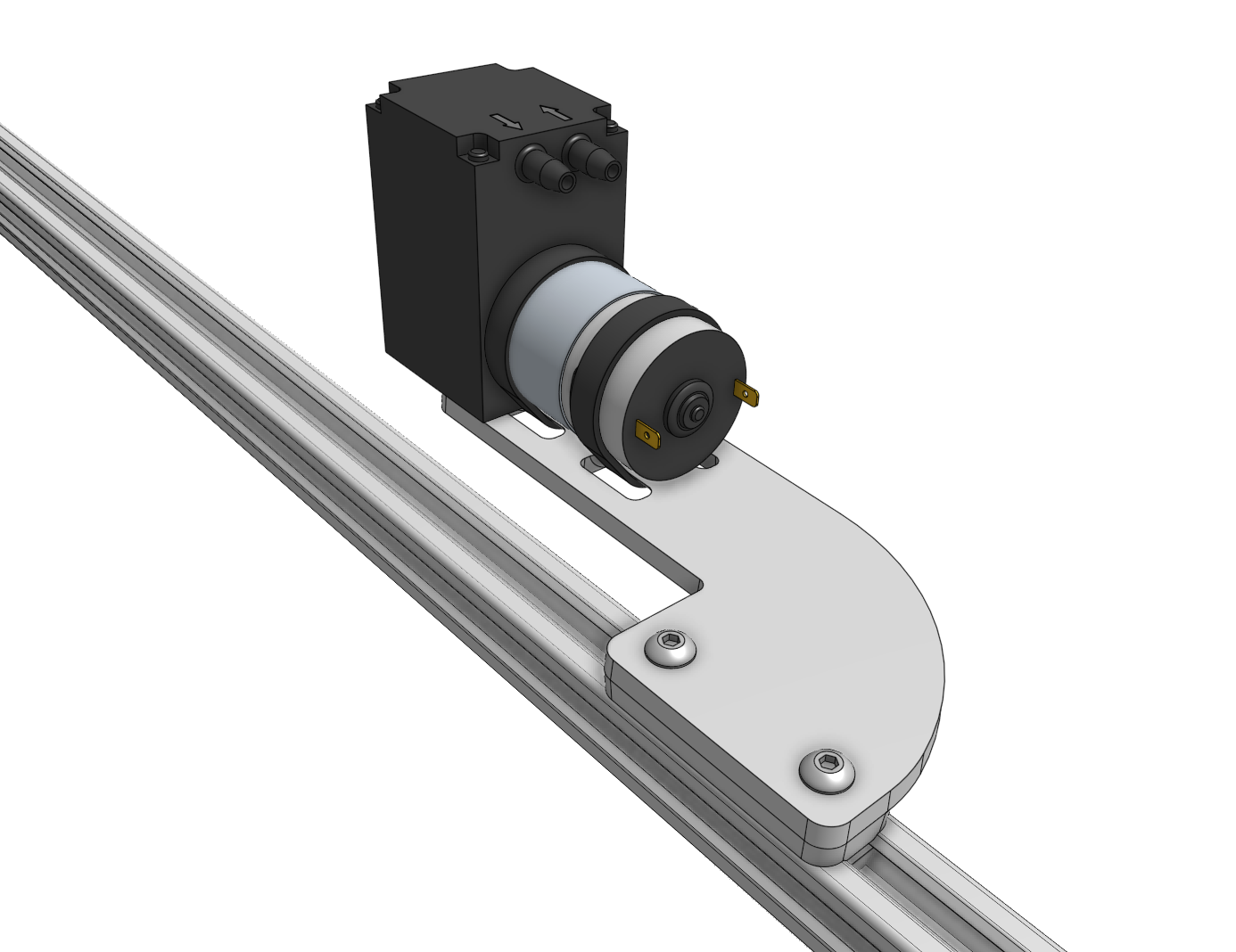
Securely tighten the vacuum pump onto the vacuum pump mount using two 200mm zip ties. Cut off the excess zip tie material.
Press one of the vacuum tubes onto the inlet of the vacuum pump. Then press the inline filter onto the open end of the tube. Then press the second vacuum tube onto the open end of the inline filter.
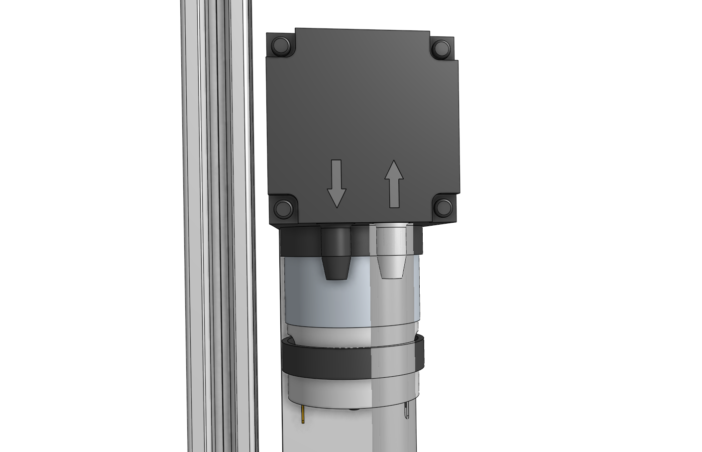

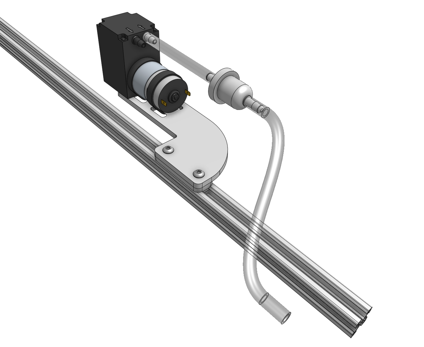
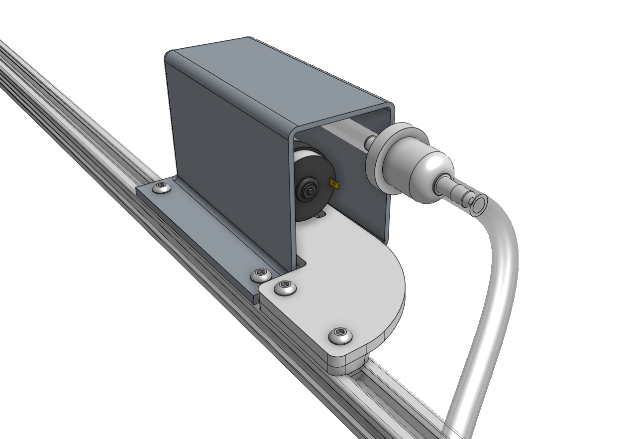
Attach the vacuum pump housing to the z-axis extrusion using two M5 x 10mm screws and 10mm nut bars.
Step 2: Mount the cable carrier supports
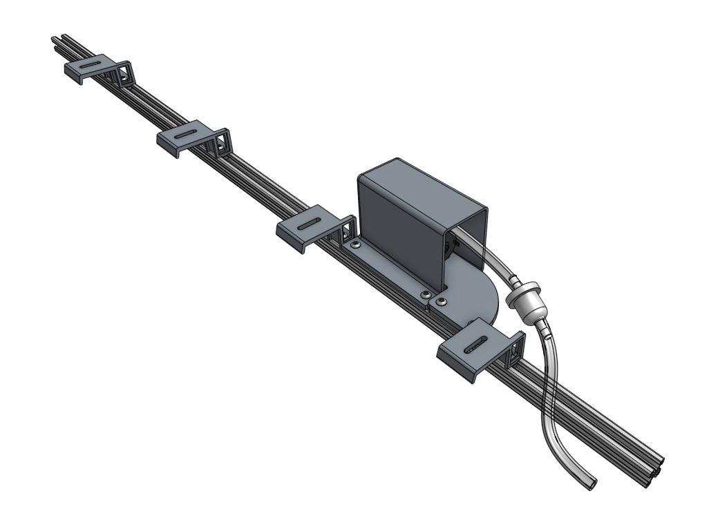
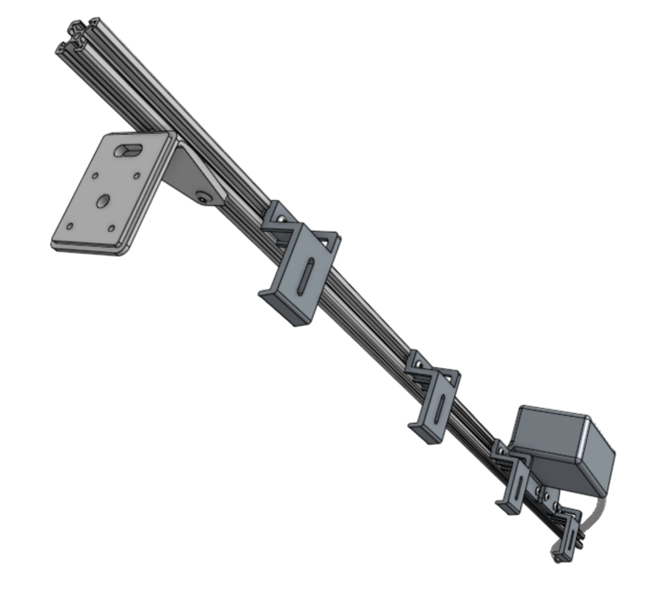
Attach the four 40mm vertical cable carrier supports to the z-axis extrusion using M5 x 10mm screws and 40mm nut bars. The space between all supports should be 180mm.
Step 3: Mount the motor
Attach the z-axis motor mount to the z-axis extrusion using two M5 x 10mm screws and one 60mm nut bar. The recessed lip of the motor mount should be 60mm from the top of the extrusion.
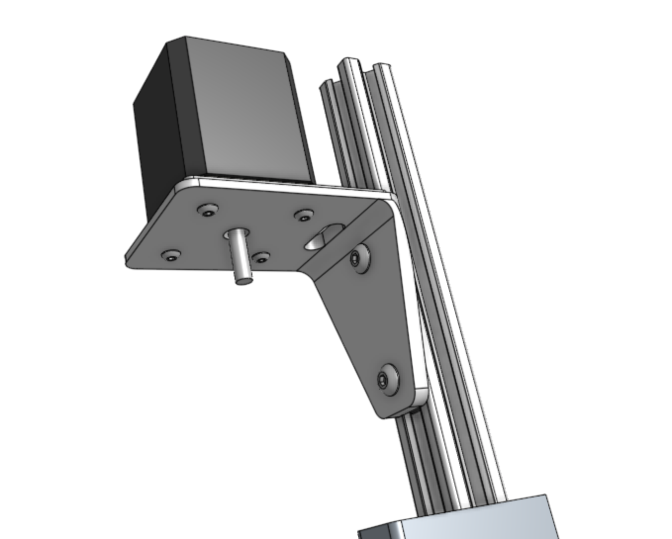
Position the motor on the mount with the motor’s connector facing the extrusion. Then secure the motor in place with four M3 x 12mm screws.
The following step requires the z-axis cable carrier to be loaded with cables and tubing before installing in the z-axis. Do not proceed unless you have the cable carrier loaded.
Step 4: Mount the cable carrier
Position the loaded z-axis cable carrier in the cable carrier supports such that the camera is located at the bottom of the extrusion. Secure the cable carrier to the vertical cable carrier support using two M5 x 16mm screws and M5 flange locknuts.
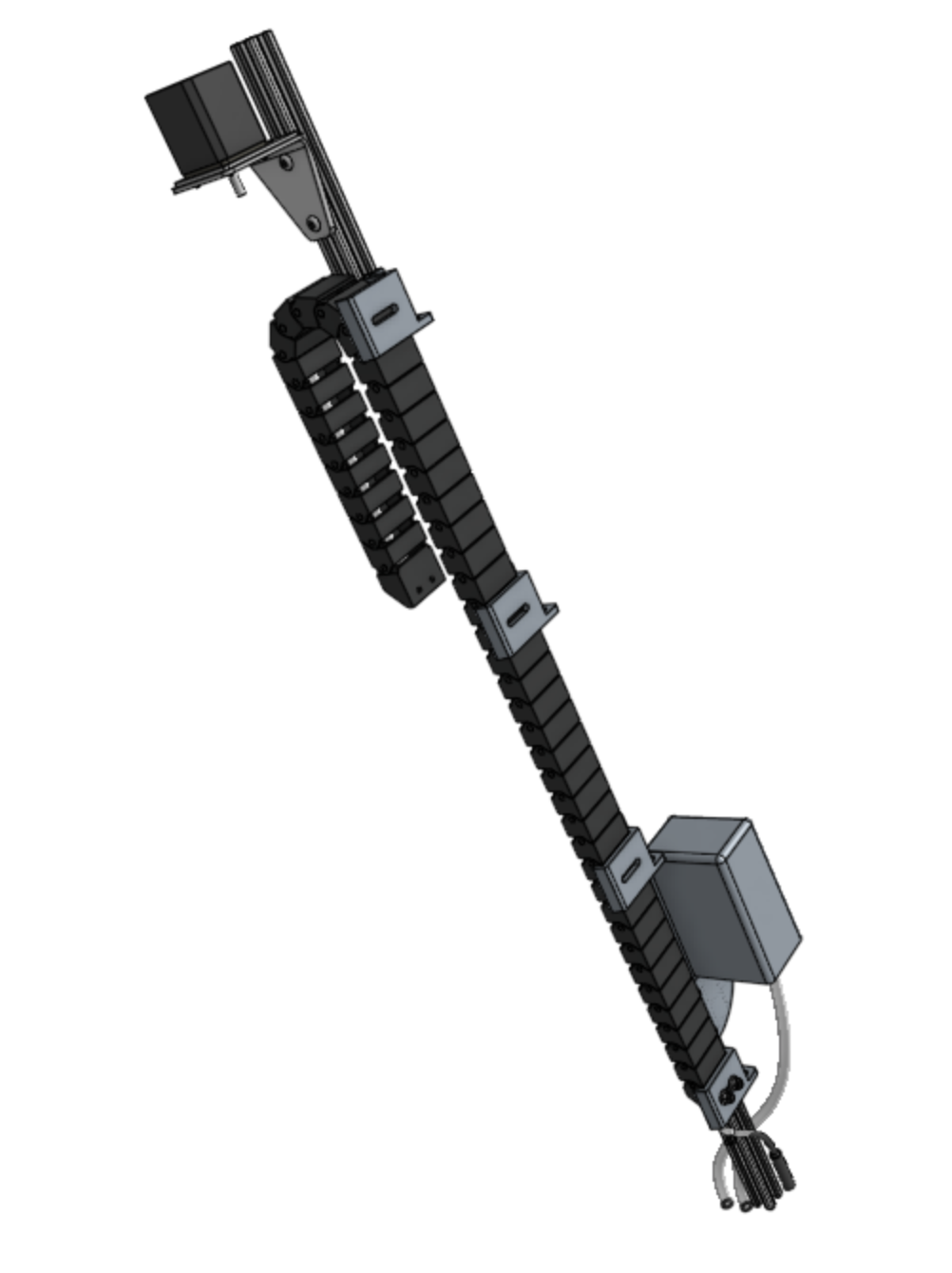

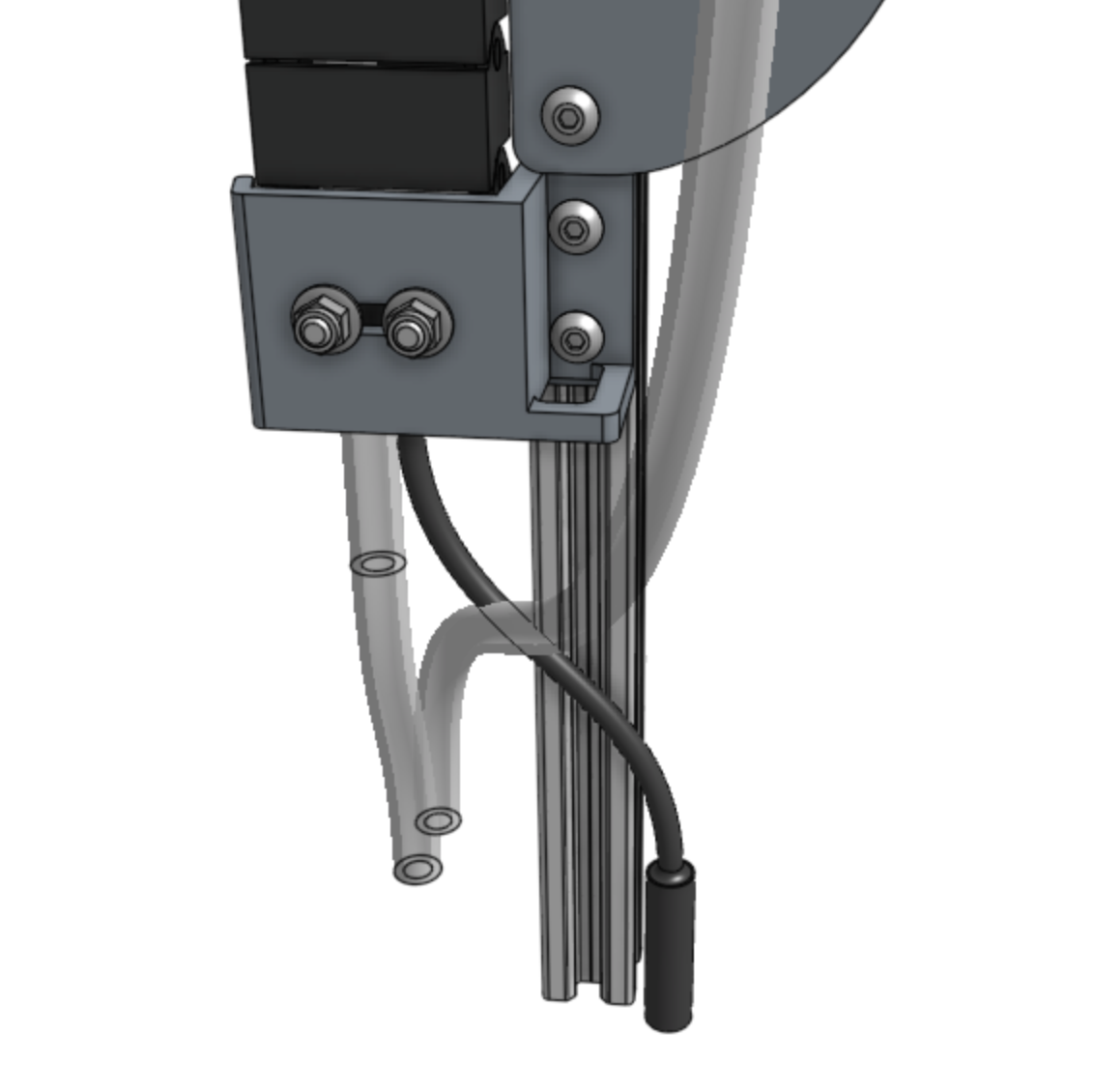
Note: not all cables are shown
Step 5: Connect the z-axis motor cable
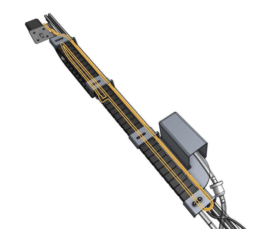
Feed the z-axis motor cable up through the slots in the four cable carrier supports and the slot in the z-axis motor mount. Then plug the cable into the motor.
Step 6: Connect the vacuum pump cable
Feed the vacuum pump cable up through the slot in the first cable carrier support and then plug the connectors into the vacuum pump’s terminals.
Step 7: Mount the motor housing
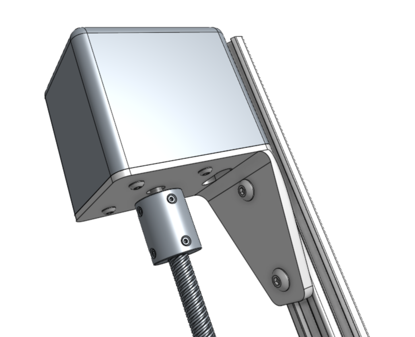
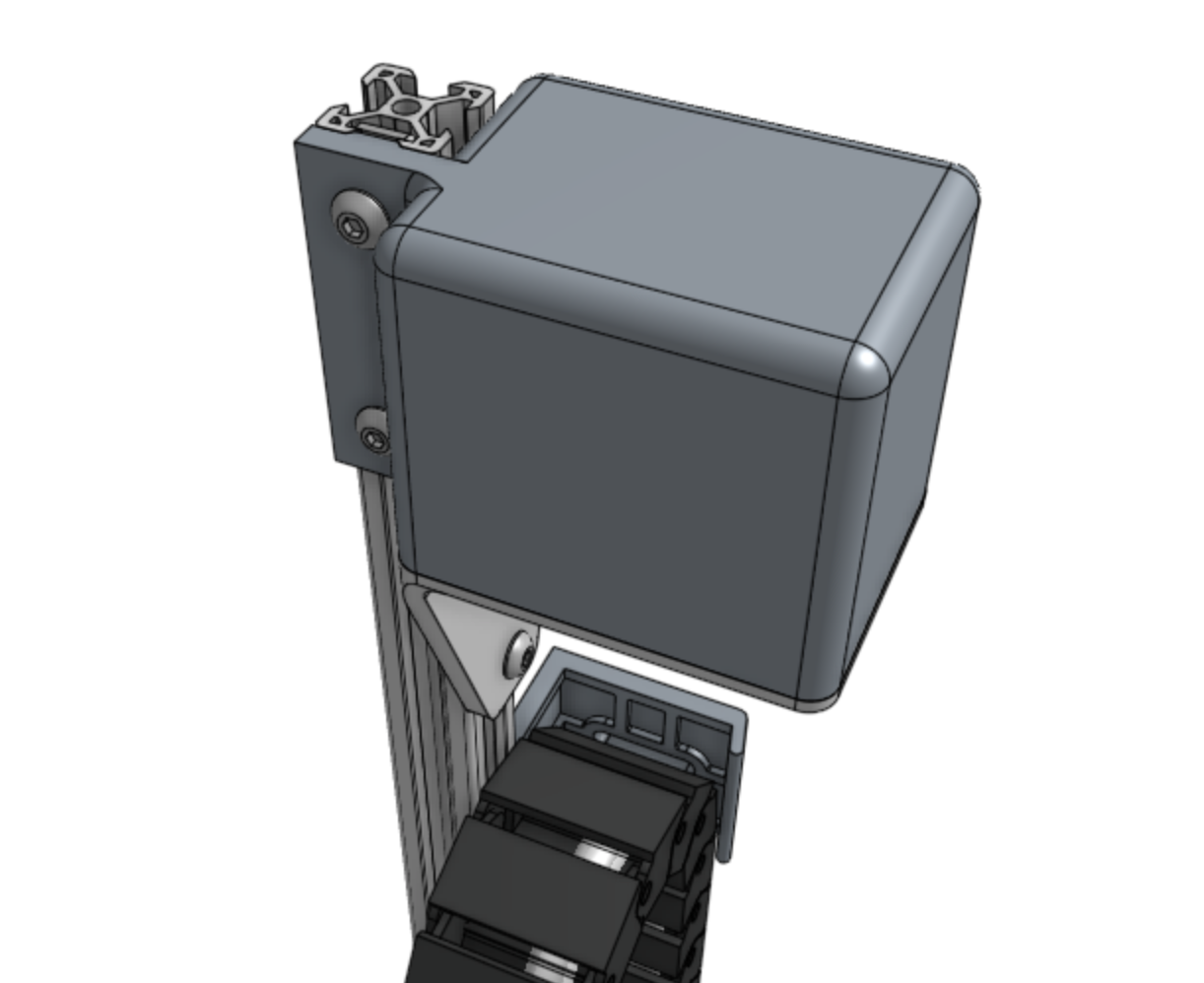
Mount the 50mm vertical motor housing using two M5 x 10mm screws and one 60mm nut bar. The housing should fit snugly in the motor mount’s recessed lip. The top of the motor housing should also be flush with the top of the extrusion, which may require a slight adjustment of the motor mount’s position.
Step 8: Attach the leadscrew
Insert the leadscrew fully into the shaft coupler and tighten the setscrews.
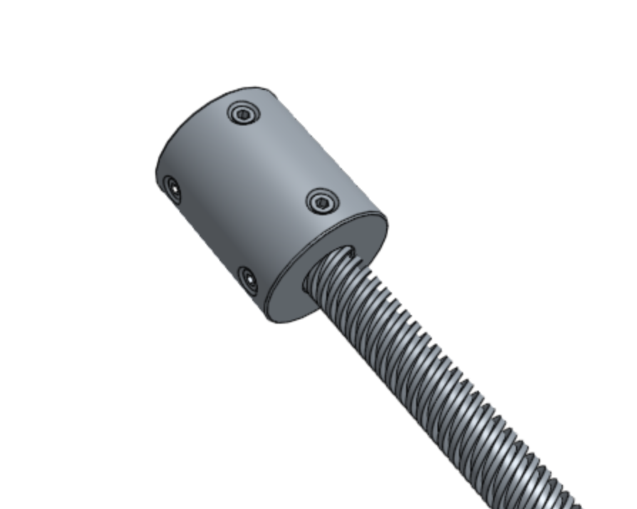
Slide the shaft coupler onto the motor shaft, ensuring that the setscrews are aligned with the flat sides of the motor shaft. Ensure there is approximately 1-3mm of space between the end of the motor shaft and the end of the leadscrew - they should not be touching inside the coupler. Tighten the setscrews.
