Plug Everything In
- Step 1: Connect the Y motor
- Step 2: Connect the water tubes
- Step 3: Check for leaks
- Step 4: Connect the Z-axis cables
- Step 5: Route the X2 motor cable and LED strip
- Step 6: Route all cables behind the electronics box
- Step 7: Plug everything in
- Step 8: Flash FarmBot OS to the microSD card
- Step 9: Mount the power supply
- Step 10: Plug FarmBot into the power source
- What’s next?
Power should still be disconnected
At this time, FarmBot should not be plugged into any power source.
Step 1: Connect the Y motor
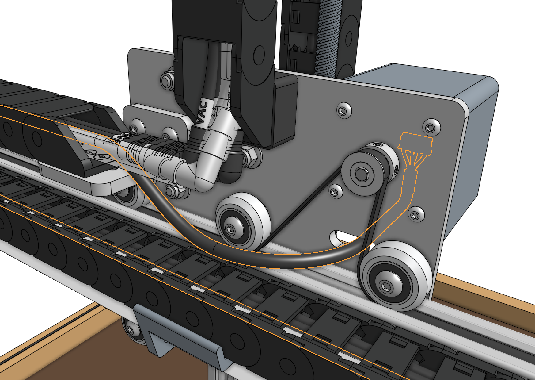
Route the Y motor cable through the slot in the cross-slide plate and connect it to the Y motor.
Step 2: Connect the water tubes
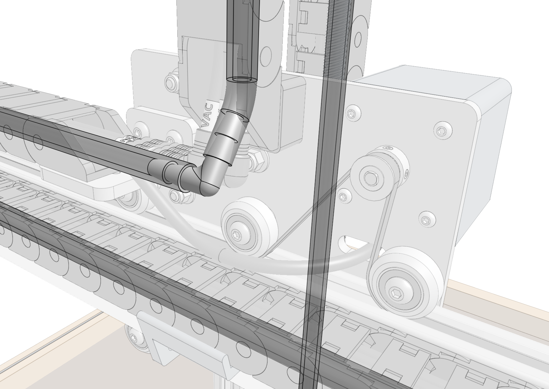
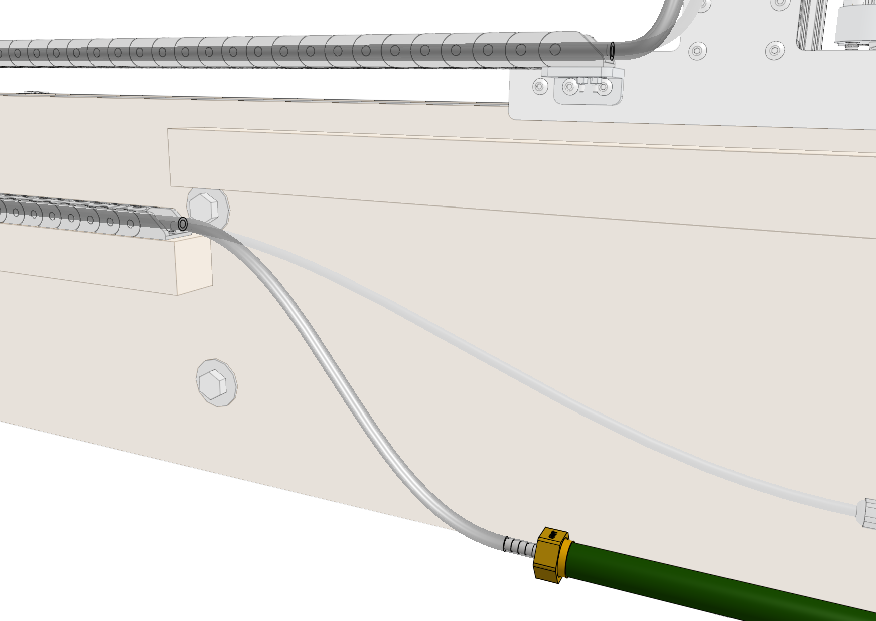
Connect the water tube coming from the y-axis cable carrier to the 90-degree barb and the NPT to barb adapter above the solenoid valve.

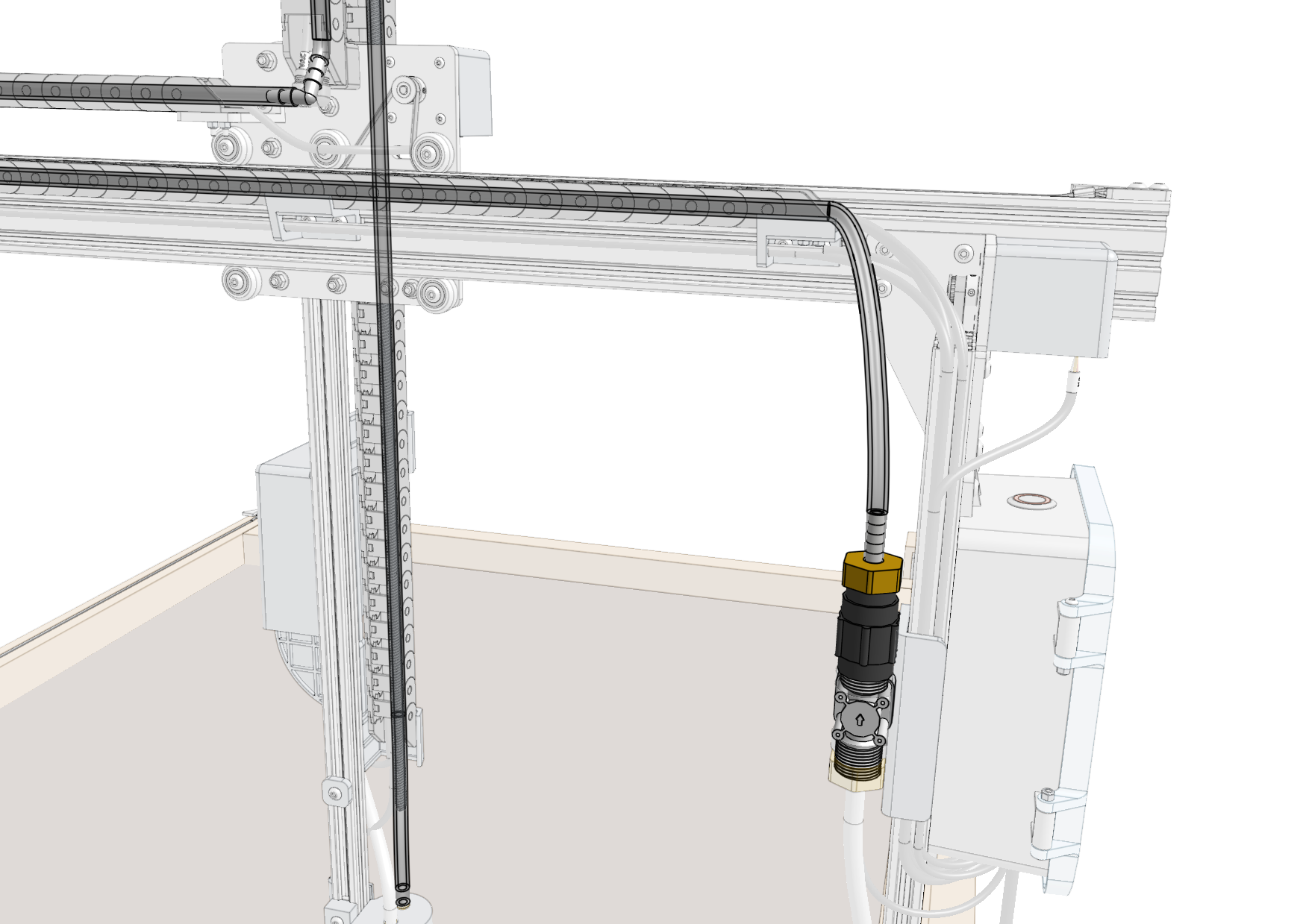
Connect the water tube coming from the top of the x-axis cable carrier to the NPT to barb adapter below the solenoid valve.
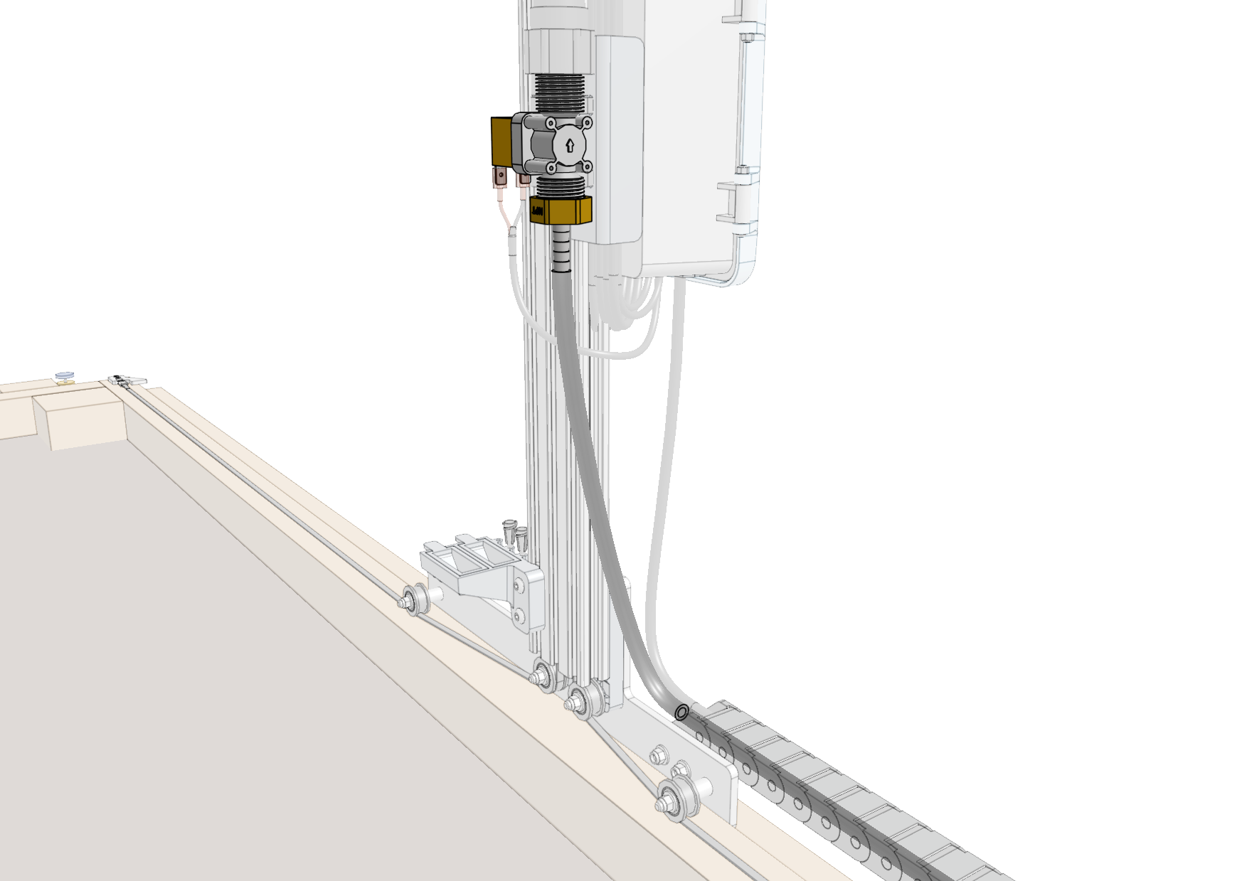
Screw the garden hose to barb adapter onto a garden hose of the appropriate length. Then connect the water tube coming from the bottom of the x-axis cable carrier to the garden hose to barb adapter.
Step 3: Check for leaks
Turn on the supply of water at your garden hose spigot and check the FarmBot for any leaks. If your municipal water pressure is abnormally high, you may need to add zip ties to the tube-to-barb connections to prevent the tubes from popping off. In rare circumstances you also may need to add plumber’s tape (PTFE tape) to the threaded connections at the hose or solenoid valve to prevent leaking.
Step 4: Connect the Z-axis cables
Connect the cables at the junction of the y-axis and z-axis cable carriers:
- Vacuum pump cables labeled
VAC - Z motor cables labeled
ZYandZZ - Camera cables labeled
CAM
The camera and z motor cables use the same connectors
Pay close attention to the cable labels to ensure you are connecting CAM to CAM and ZY to ZZ. Take your time with this step because a mistake could permanently damage the electronics.
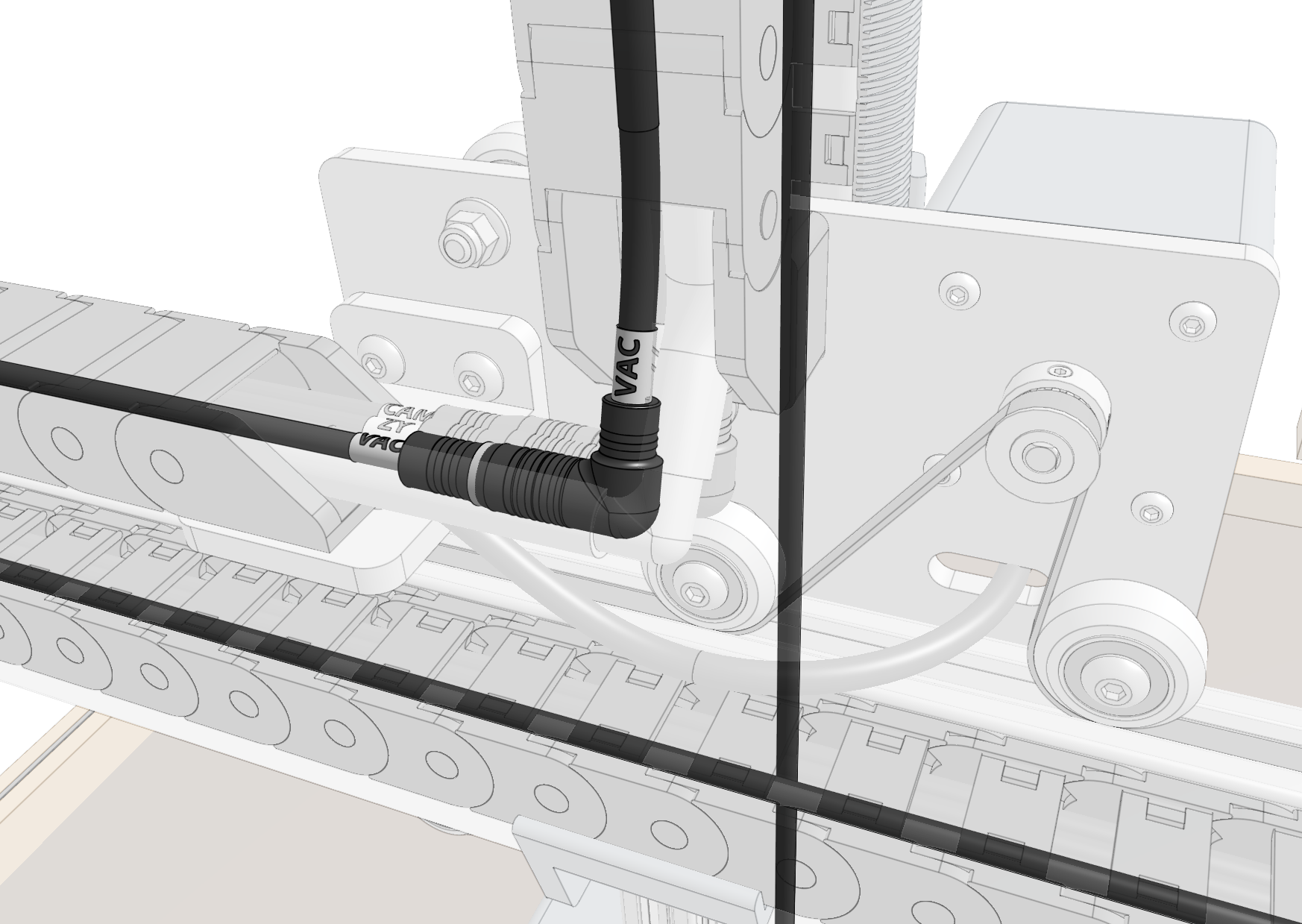

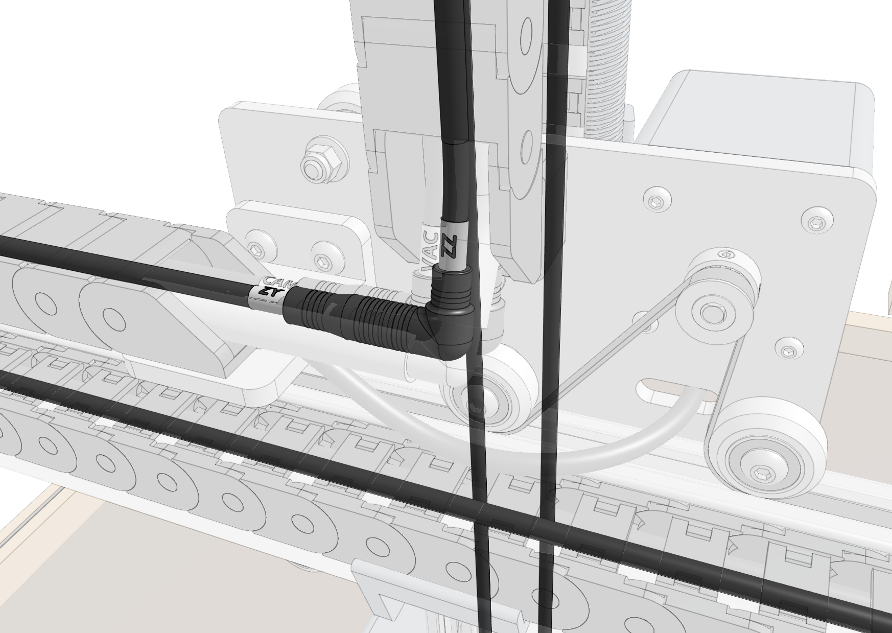
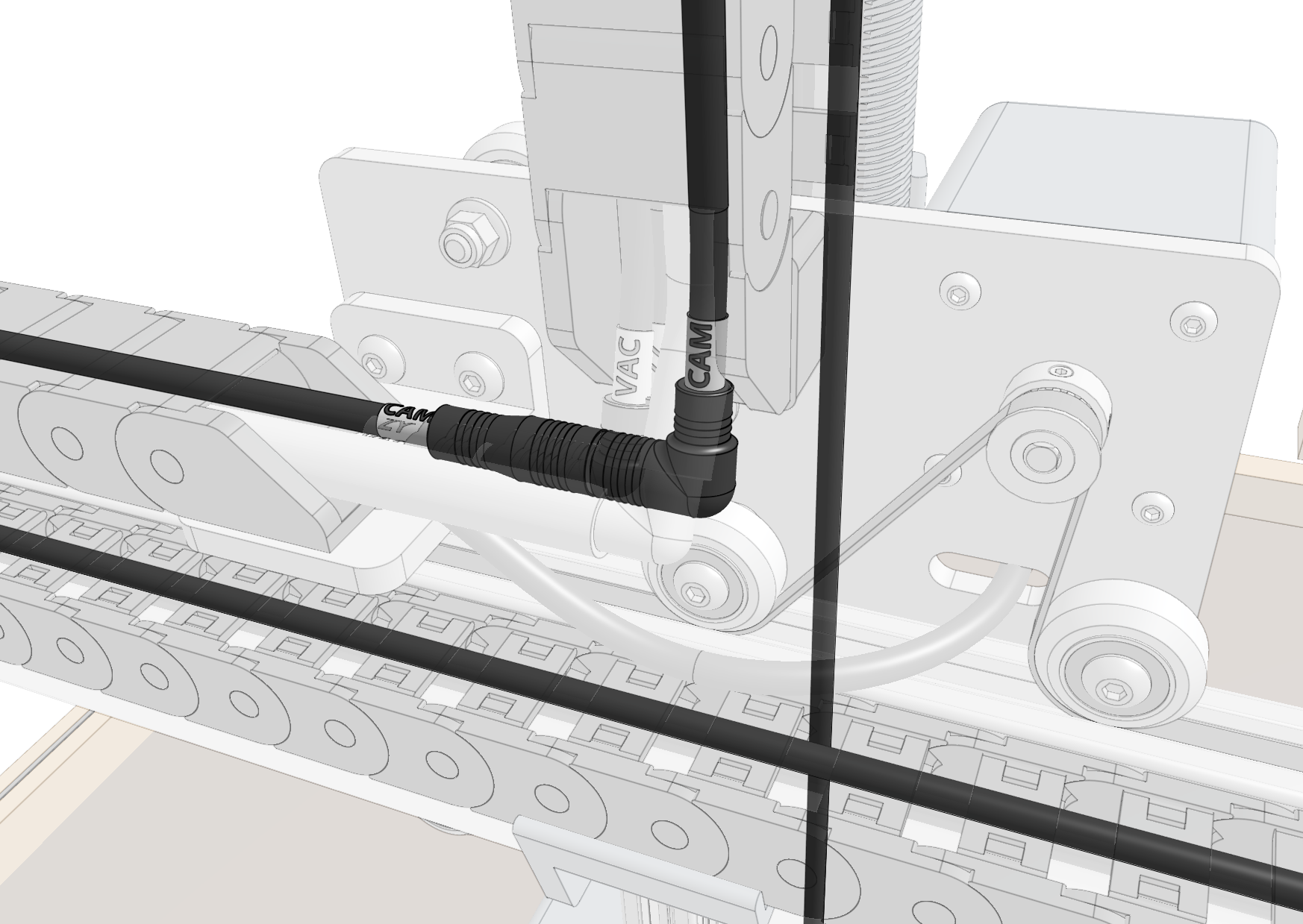
Pay special attention that you fully insert the 90-degree connectors together. This may require a multi-step process of pushing together, slightly tightening the thumb screws, pushing together again, and tightening some more. See the video below for detail.
Step 5: Route the X2 motor cable and LED strip
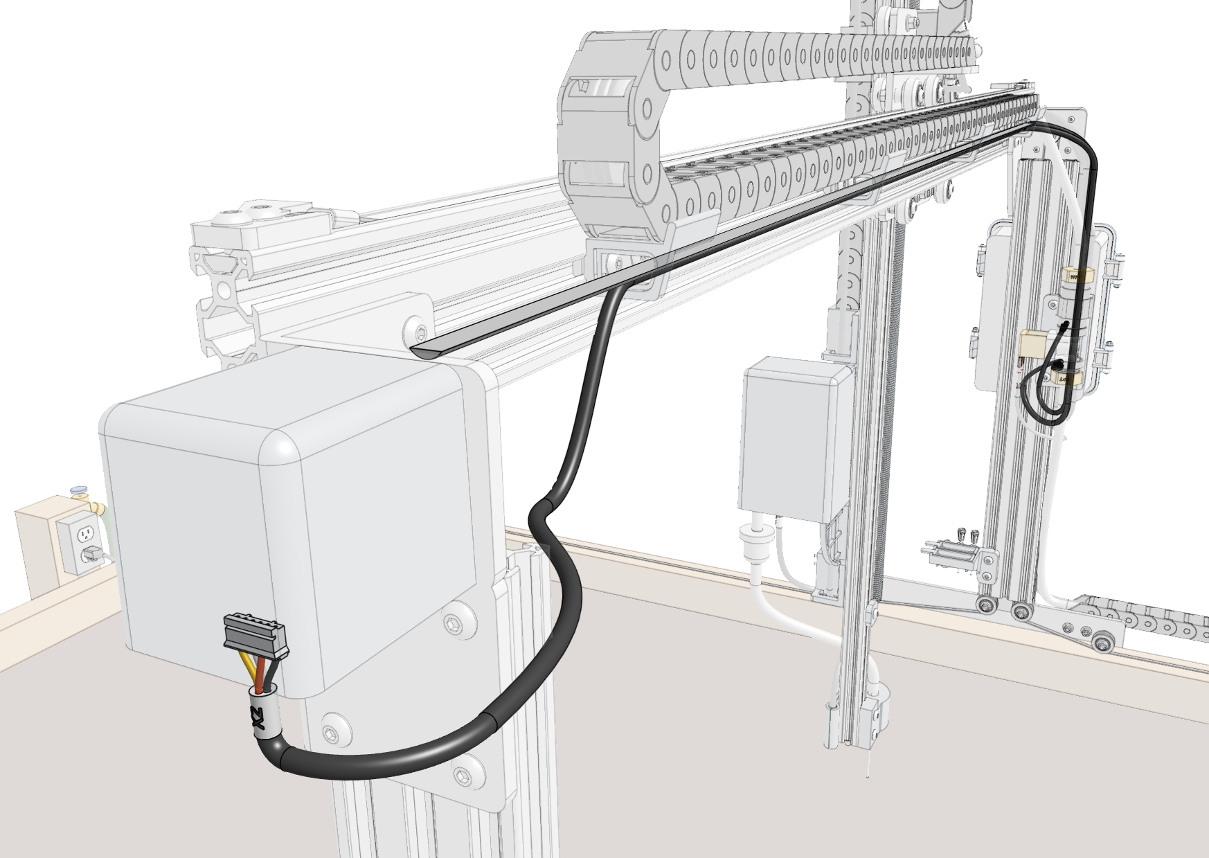
Attach the X2 motor cable to the X2 motor. Then route the cable and the LED strip through the 30mm horizontal cable carrier supports along the gantry main beam.
Step 6: Route all cables behind the electronics box
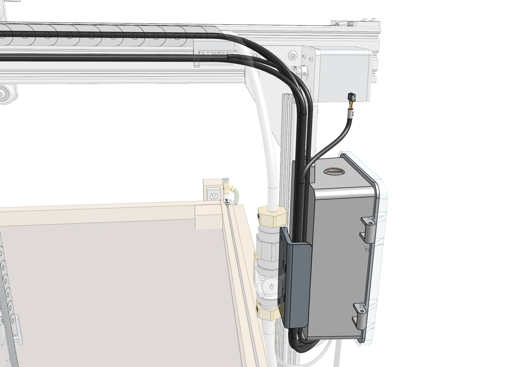
Route all of the cables down between the solenoid valve mount and the electronics box. You may need to temporarily disconnect the solenoid valve mount from the extrusion to facilitate fitting all of the cables in the space.
Step 7: Plug everything in
Power should still be disconnected
At this time, the FarmBot should not be plugged into any power source.
The diagram below illustrates the FarmBot Express electronics schematic. In the following steps you’ll connect each motor and peripheral one at a time, and finally the power supply.
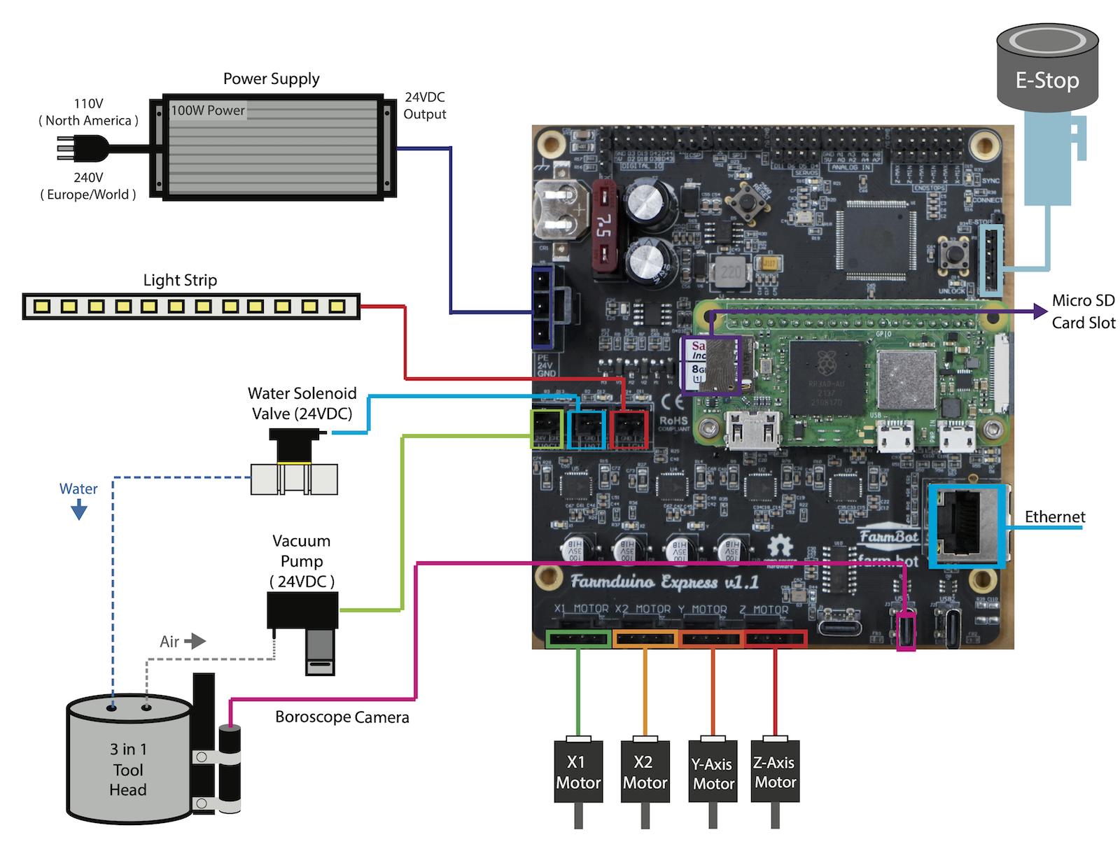
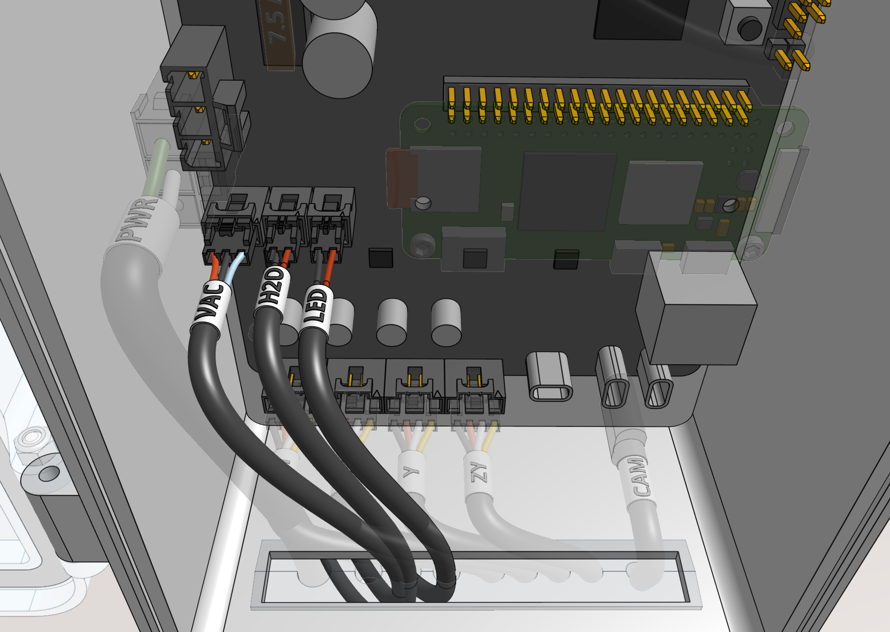
Connect the peripheral cables to the Farmduino Express board. From left to right:
- Vacuum pump cable labeled
VACto theVACUUMconnector. - Solenoid valve cable labeled
H20to theWATERconnector. - LED strip labeled
LEDto theLIGHTINGconnector.
Connect the motor cables to the Farmduino Express board. From left to right:
- Cable labeled
X1to theX1 MOTORconnector. (this should be pre-connected) - Cable labeled
X2to theX2 MOTORconnector. - Cable labeled
Yto theY MOTORconnector. - Cable labeled
ZYto theZ MOTORconnector.
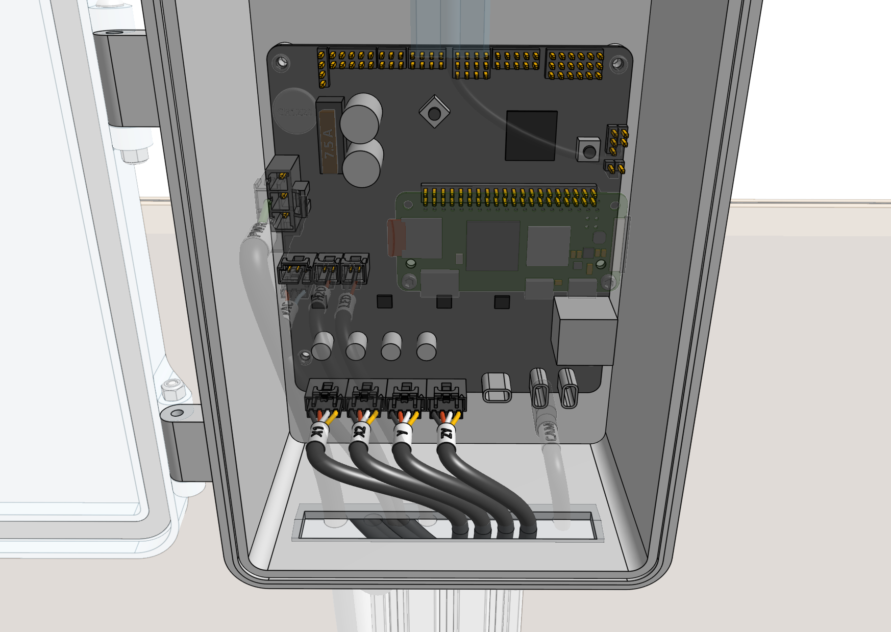
Connect the camera cable to one of the vertically oriented USB Type-C connectors labeled USB1 or USB2 on the Farmduino Express board.
Do not use the horizontally oriented USB Type-C connector
Plugging the camera into the horizontally oriented connector will prevent the Raspberry Pi from communicating with the Farmduino.
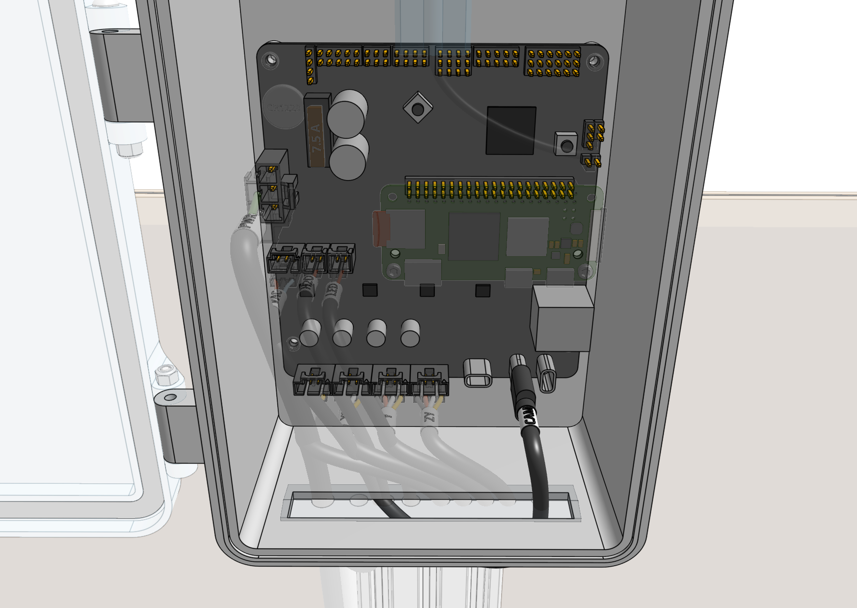
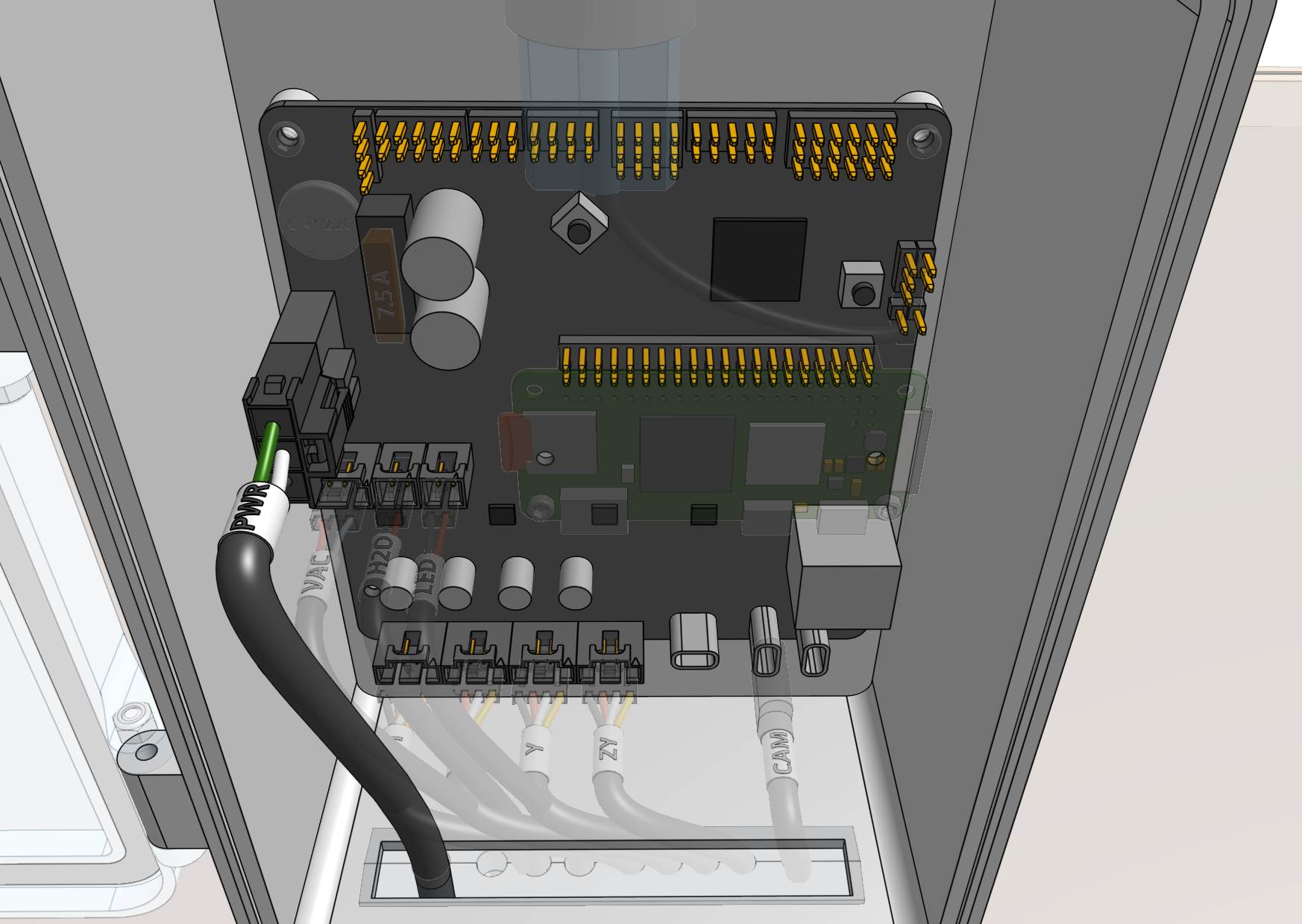
Connect the power supply cable to the 24V POWER IN connector on the Farmduino Express board.
Step 8: Flash FarmBot OS to the microSD card
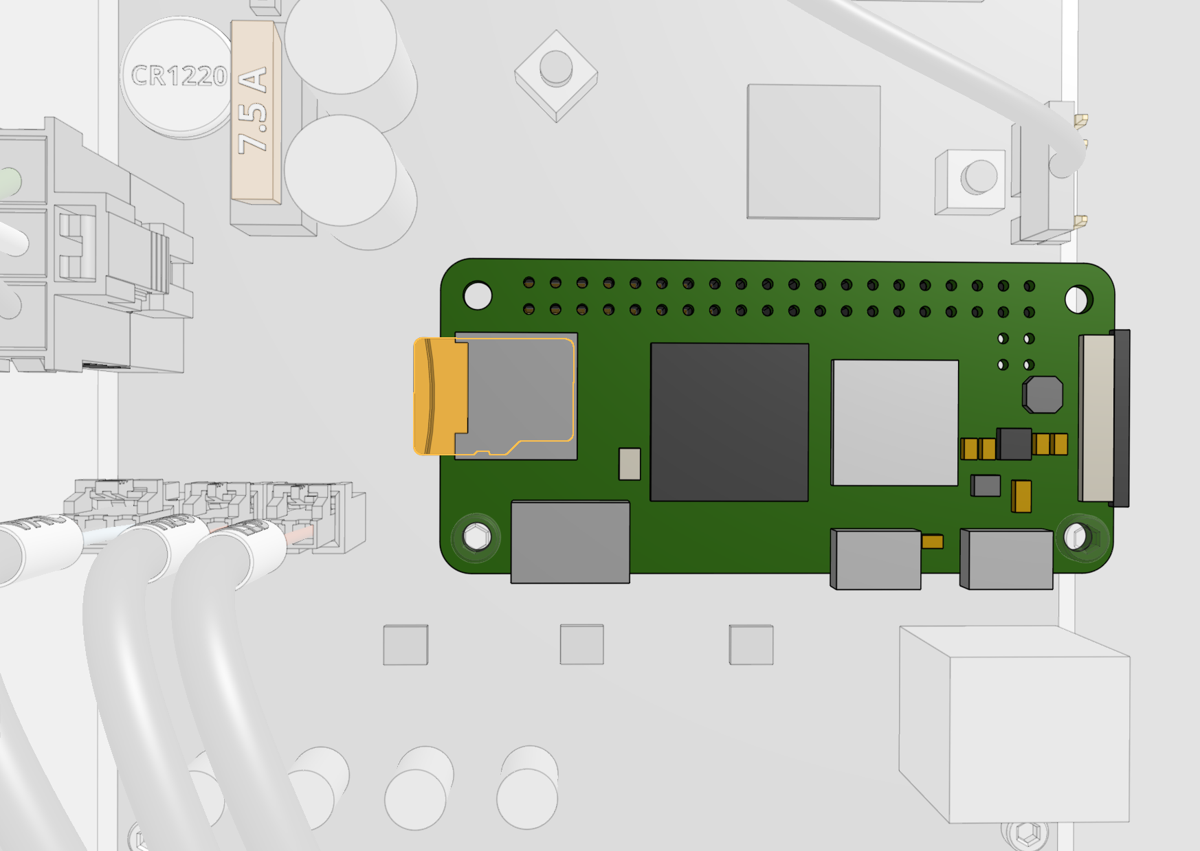
Remove the micro SD card from the Raspberry Pi Zero and follow our FarmBot OS installation instructions to install the latest version of our software. Then reinsert the microSD card into the Pi.
Step 9: Mount the power supply
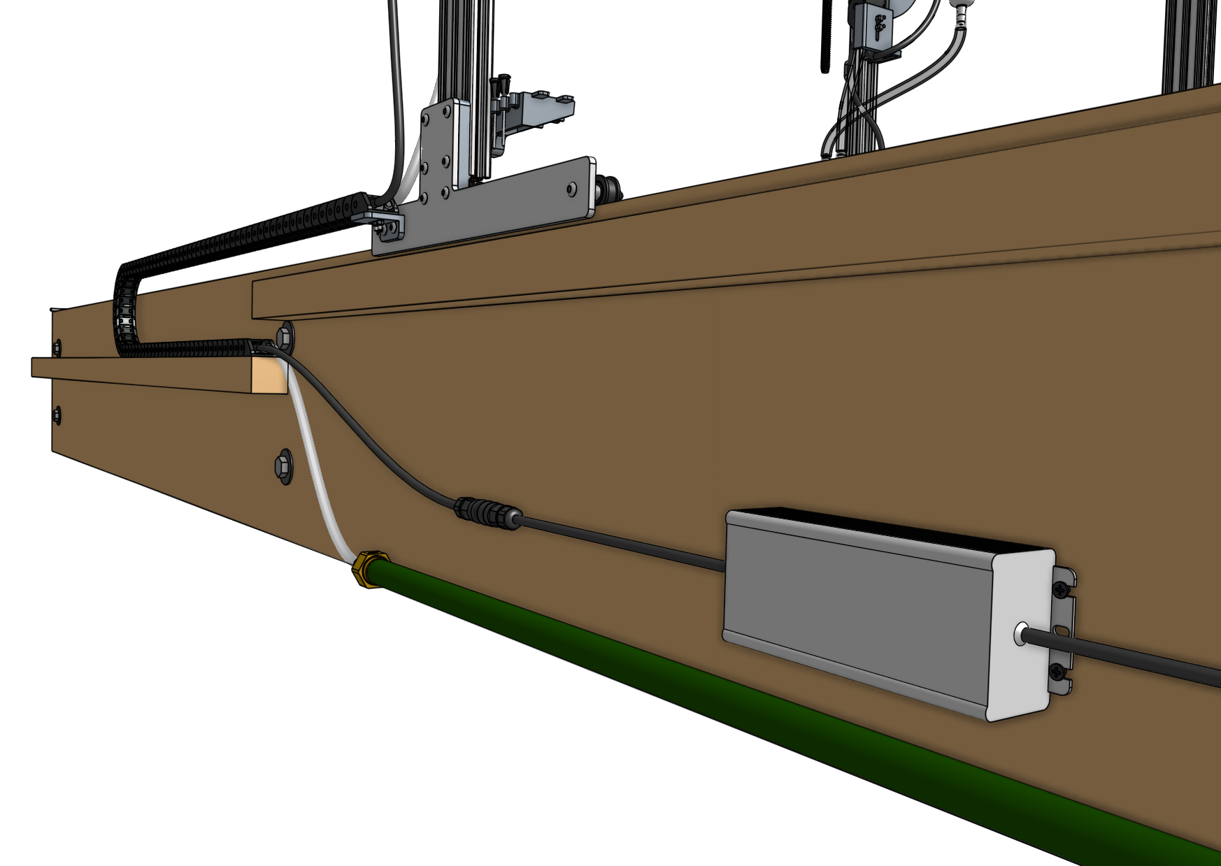
Mount the power supply to the bed using four wood screws. Then connect the power supply’s output to the power supply cable.
Step 10: Plug FarmBot into the power source
Before plugging in...
Once you plug in the power supply, your system will be powered. Once powered, you cannot add, remove, or change any motor cables, peripheral cables, etc, or you risk damaging the electronics and being electrically shocked.
If you need to make any changes, first unplug the power supply from the wall.
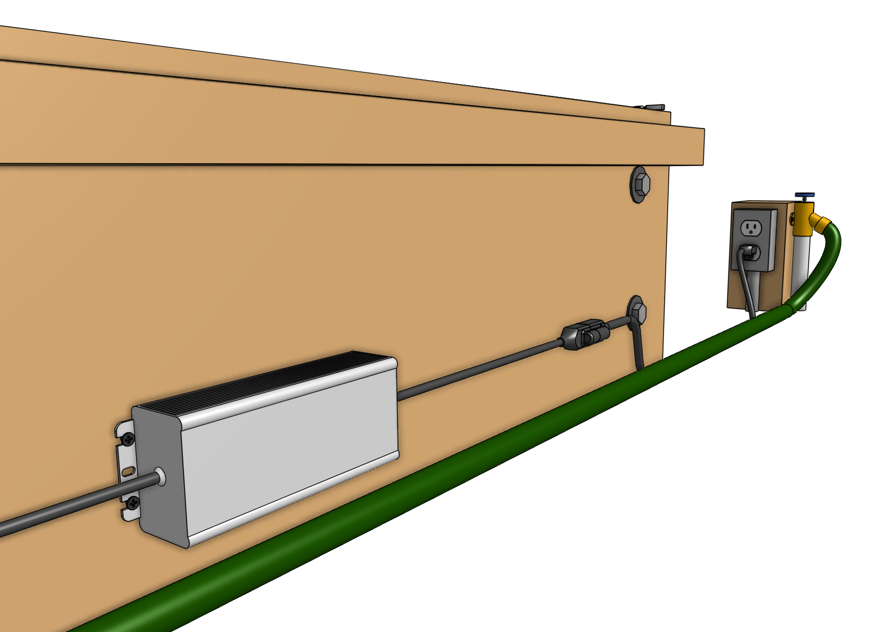
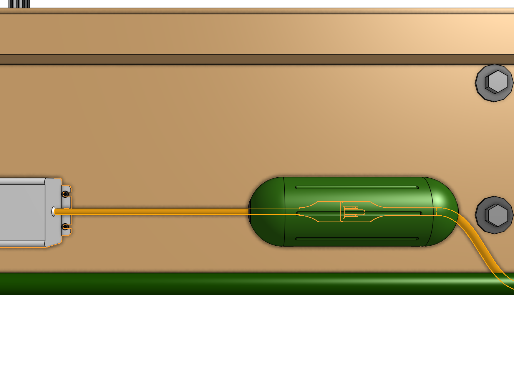
If everything looks good, and you understand the precautions needed around powered electronics, plug the power supply into a GFCI protected outlet. If an appropriate outlet is not close enough to plug in directly, use an extension cord of the appropriate length and the green power cord protector.

The mark of success
If all has gone well, FarmBot will begin booting up and you should see blinking lights!
If anything seems not right, suspicious, or hazardous, immediately unplug the power supply from the wall and contact us at contact@farm.bot.